Synchronous rectifying control method and circuit

A technology of synchronous rectification and control method, applied in the control/regulation system, the conversion of DC power input to DC power output, the conversion of AC power input to DC power output, etc., can solve the problems of low efficiency, inaccurate control of switching time of synchronous rectifier, Problems such as large power loss, to achieve the effect of reducing power loss, avoiding negative current, and high working efficiency

Active Publication Date: 2013-01-16
SILERGY SEMICON TECH (HANGZHOU) CO LTD
View PDF4 Cites 39 Cited by
  • Summary
  • Abstract
  • Description
  • Claims
  • Application Information

AI Technical Summary

Problems solved by technology

[0008] The purpose of the present invention is to provide a new type of synchronous rectification control circuit and synchronous rectification control method to solve the problems of large power loss, low efficiency, inaccurate switching time control of synchronous rectifiers in the prior art and problems in light load state negative current problem

Method used


Image

  • Synchronous rectifying control method and circuit
  • Synchronous rectifying control method and circuit
  • Synchronous rectifying control method and circuit

Examples


Embodiment Construction

[0061] Several preferred embodiments of the present invention will be described in detail below with reference to the accompanying drawings, but the present invention is not limited to these embodiments. The present invention covers any alternatives, modifications, equivalent methods and schemes made on the spirit and scope of the present invention. In order to provide the public with a thorough understanding of the present invention, specific details are set forth in the following preferred embodiments of the present invention, but those skilled in the art can fully understand the present invention without the description of these details.

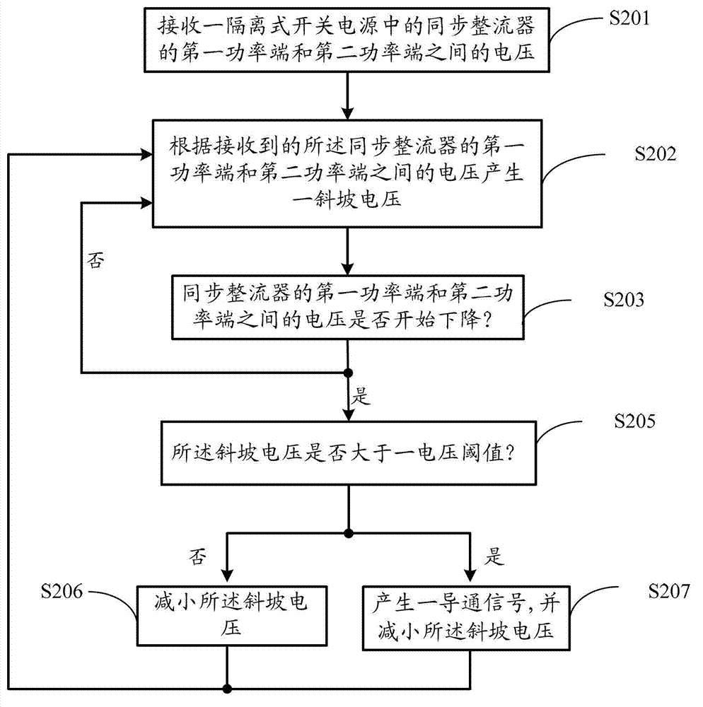
[0062] refer to figure 2 , shows a flow chart of a synchronous rectification control method applied to an isolated switching power supply according to an embodiment of the present invention. In this embodiment, the synchronous rectification control method includes the following steps:

[0063] S201: Receive the voltage between the firs...


PUM


Abstract

The invention discloses a synchronous rectifying control method and circuit for an isolated switching power supply. According to the synchronous rectifying control method in the embodiment of the invention, the switching-off moment of a main power device on the primary side is judged accurately according to the peak value of the ramp voltage between the first power end and the second power end of a synchronous rectifier, and the synchronous rectifier is started timely, thus the interval between the switch-off moment of the main power device and the switch-on moment of the synchronous rectifier is reduced as mush as possible, the power loss is reduced, and the highest work efficiency can be achieved.

Description

technical field [0001] The invention relates to the technical field of semiconductors, in particular to a synchronous rectification control method and a synchronous rectification control circuit of a synchronous rectifier in a switching power supply using a power transformer. Background technique [0002] A conventional isolated power supply includes one or more primary side switches, at least one transformer and one or more rectifiers on the secondary side. The transformer is used to provide a relatively large voltage conversion ratio, implement more reliable short-circuit protection for the input source, and realize the isolation between the primary side and the secondary side that meets the requirements of safety regulations. The rectifier is used to rectify the AC voltage or current of the secondary winding of the transformer to generate the DC voltage or current required by the output load. Common transformer-based switching power supply topologies include flyback, for...

Claims


Application Information

Patent Timeline
Patent Type & Authority Applications(China)
IPC IPC(8): H02M3/335H02M7/217
CPCY02B70/1475H02M3/33523H02M3/33592Y02B70/10
Inventor 姚杰赵晨
Owner SILERGY SEMICON TECH (HANGZHOU) CO LTD
Why Eureka
Try Eureka