
Controllable constrained laser micro shot peening intensification device and method thereof

A shot peening and laser technology, applied in the field of laser processing and surface modification, can solve the problems of difficult to accurately control depth, low cost, weak plasma, etc., and achieve the effect of reducing interval time and improving efficiency

Inactive Publication Date: 2017-05-10
CHINA UNIV OF MINING & TECH
View PDF6 Cites 9 Cited by
  • Summary
  • Abstract
  • Description
  • Claims
  • Application Information

AI Technical Summary

Problems solved by technology

When laser micro-peening is strengthened, the plasma generated by the low-energy pulse laser is weak, and there is a bonding gap between the K9 glass and the surface of the metal material, which cannot completely seal the plasma, which seriously affects the effect of laser micro-peening
The flowing deionized water curtain can adapt to the surface of different shapes of the parts, and it is tightly attached to the surface of the parts. It is low in cost, good in light transmission, and can be recycled. There are also problems that are difficult to overcome in the ionized water curtain: (1) Because the depth of the flowing deionized water is difficult to accurately control, it affects the stability of the plasma confinement during the laser micro-peening process, so that the laser micro-peening effect is not very good control
(2) The vaporized deionized water at the laser focus forms bubbles, which cannot be quickly taken away by natural water flow, thus affecting the incidence of subsequent laser pulses, so enough time should be left between two adjacent laser pulses to Purification of the focus area seriously affects the efficiency of laser micro-peening

Method used


Image

  • Controllable constrained laser micro shot peening intensification device and method thereof
  • Controllable constrained laser micro shot peening intensification device and method thereof

Examples


Embodiment Construction

[0016] The present invention will be further explained below in conjunction with the accompanying drawings.

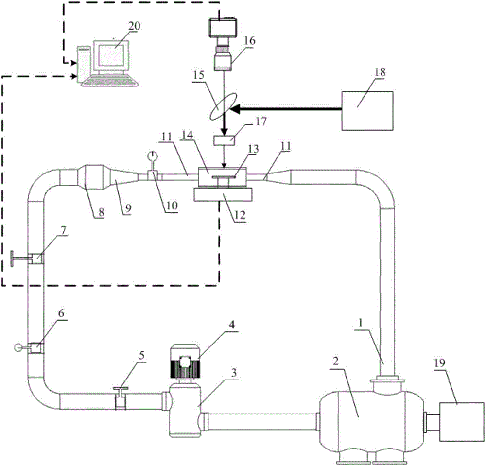
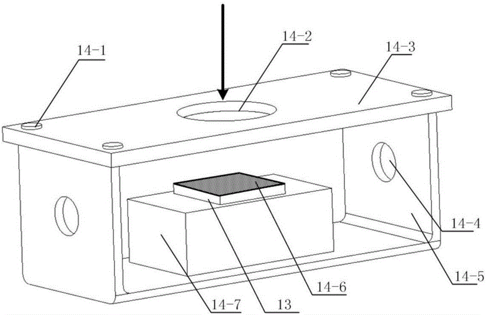
[0017] Such as figure 1 As shown, a controllable and constrained laser micro-peening strengthening device includes a water pipeline 1 for deionized water circulation; a water storage tank 2 for storing deionized water; and is used for inputting deionized water into the circulating water system Energy motor 4 and hydraulic pump 3; flow control valve 5 for controlling the flow of deionized water in the circulating water system; flowmeter 6 for measuring the flow of deionized water in the circulating water system; Pressure control valve 7 for pressure in deionized water; buffer section 8 for stabilizing deionized water; shrinking section 9 for accelerating deionized water velocity in circulating water system; pressure gauge for displaying deionized water pressure in circulating water system 10. The hose 11 used to connect the sample chamber 14 and the shrinkage section 9...


PUM


Abstract

The invention discloses a controllable constrained laser micro shot peening intensification device and a method thereof. The device comprises a circulating water system. A deionized water curtain is adopted as a constrained layer and is provided through the circulating water system; a high-speed camera is used for observing the growth and gathering situation of bubbles in a laser micro shot peening intensification process on line; a motor is used for driving a hydraulic pump to enable deionized water to circularly flow in the whole circulation water system; the pressure and the flow rate of the deionized water in the circulating water system are controlled to take away bubbles generated near a focal point in the laser micro shot peening intensification process so as to improve laser micro shot peening efficiency. The deionized water in the circulating water system is kept in certain pressure, so that the rigidity of the deionized water curtain on the surface of a laser micro shot peening metal sample is increased, the constraining function of the deionized water curtain for plasma explosion is improved, material surface laser-induced shock wave pressure is enhanced, and an active function is performed on improving a laser micro shot peening intensification effect.

Description

technical field [0001] The invention relates to the technical field of laser processing and surface modification, in particular to a processing method and device for laser micro-shot-peening strengthening on the surface of metal materials under controllable constraints. Background technique [0002] Laser micro-shot peening is an effective method to improve the mechanical properties of the surface of metal materials by using the force effect of laser-induced shock waves, and it has potential application prospects. [0003] When laser micro-peening strengthens the surface of metal parts, the function of the confinement layer is to limit the free diffusion of the explosive plasma, so that the force effect of the shock wave can be more concentrated on the metal surface. The commonly used confinement layer is K9 glass and flowing deionized water screen. When laser micro-peening is strengthened, the plasma generated by the low-energy pulsed laser is weak, and there is a bonding ...

Claims


Application Information

Patent Timeline
IPC IPC(8): C21D10/00
CPCC21D10/005
Inventor 杨海峰满家祥刘昊杨建华郝敬宾
Owner CHINA UNIV OF MINING & TECH
Learn More