
Lock with a releasable rotary unit

A technology of rotating unit and releasing position, which is applied in locks with spring bolts, locks operated by non-mechanical transmission, construction locks, etc.

Active Publication Date: 2009-10-07
DORMAKABA DEUT GMBH
View PDF0 Cites 1 Cited by
  • Summary
  • Abstract
  • Description
  • Claims
  • Application Information

AI Technical Summary

Problems solved by technology

[0004] The disadvantage of the known blocking devices for blocking the thumbturner unit by the stopper element is that there is a direct connection between the selector element and the stopper element, without the lock a person who can open the door can retract the stopper element to the release position to reactivate the thumbwheel

Method used


Image

  • Lock with a releasable rotary unit
  • Lock with a releasable rotary unit
  • Lock with a releasable rotary unit

Examples


Embodiment Construction

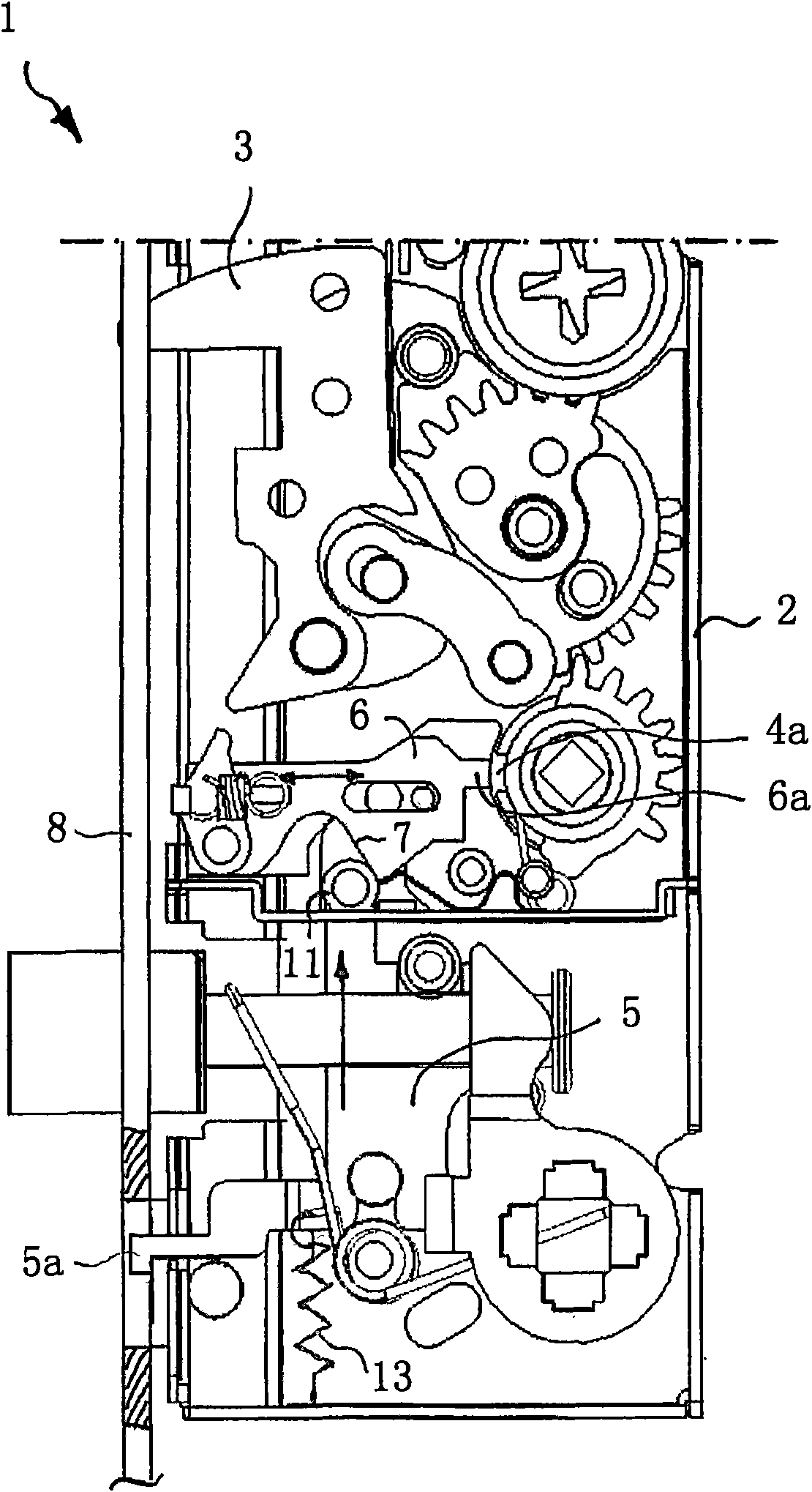
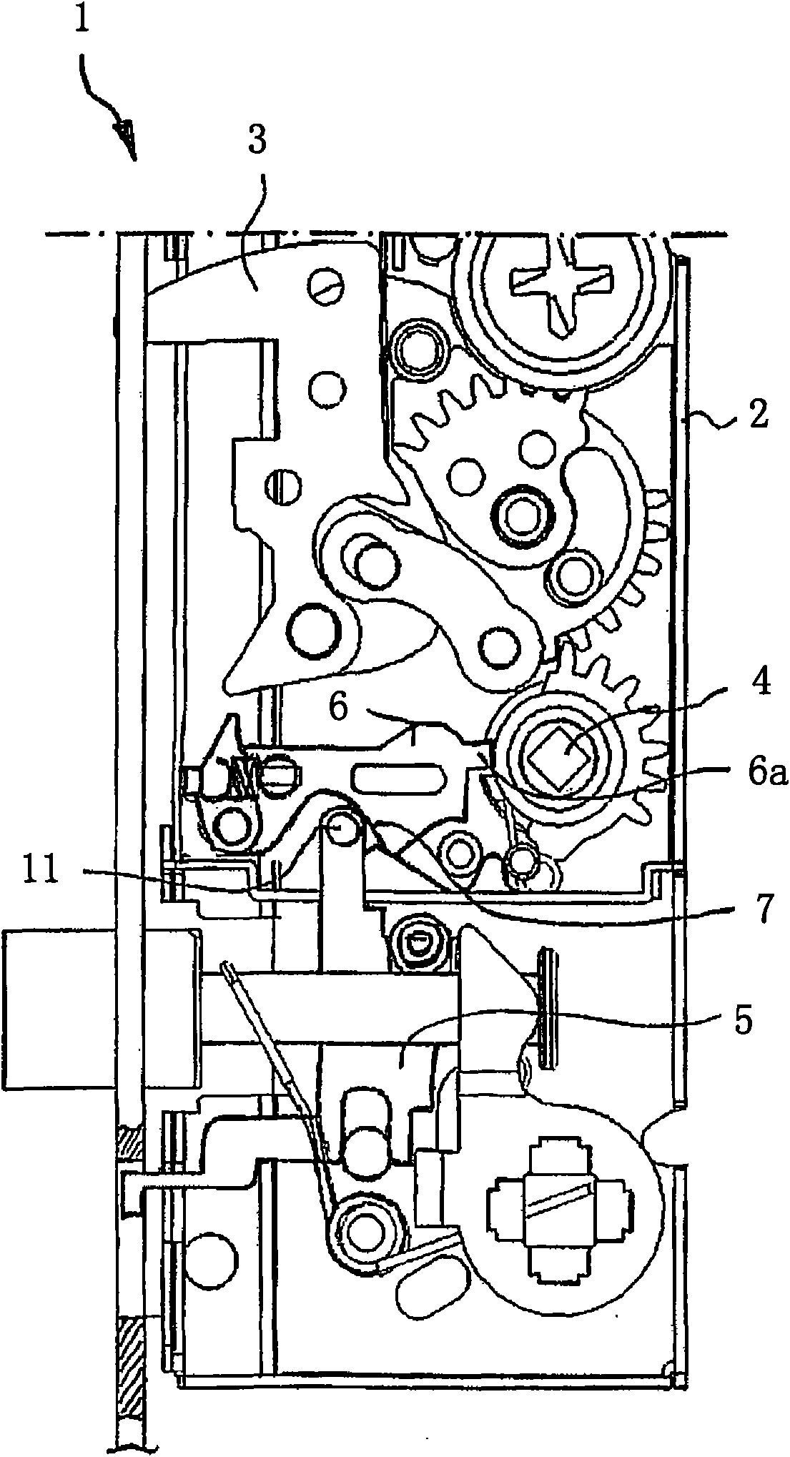
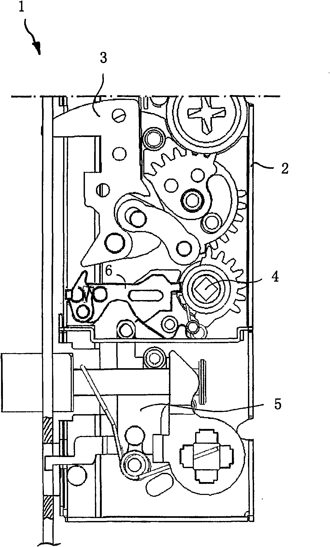
[0027] exist figure 1 In , a first embodiment of a lock 1 for doors, windows or the like according to the invention is shown, the lock 1 comprising a lock housing 2 in which the locking mechanism is accommodated. The locking mechanism comprises a lever element 3 and a swivel unit 4, which can be used to receive a thumbwheel unit. Via a mechanical connection, this swivel unit 4 interacts with said rod element 3, which is movable between an extended position and a retracted position, wherein said rod element 3 is shown in the retracted position.

[0028] The lock 1 also comprises a selector element 5 and a stop element 6 for engaging into said rotary unit 4 in order to block the rotary movement of the rotary unit 4, thereby disabling the function of the thumbwheel unit. This stop element 6 is shown in the released position, the bolt end 6 a of which is not engaged in the recess 4 a of the swivel unit 4 . In order to move the stopper element 6 between the release position and t...


PUM


Abstract

Disclosed is a lock (1) for doors, windows and the like. The lock (1) has a locking housing (2), wherein, a closing mechanics having a bolt element (3) and a rotary unit (4) is housed in the locking housing (2), the rotary unit (4) is used for receiving a rotation stopper unit, and interacts with the pole element (3), so that the bolt element (3) can move between the between salient and retracted positions. The lock (1) further includes a sector element (5) and a stop element (6) connected in the rotary unit (4), for stopping the rotation of the rotary unit (4), the stop element (6) can be transferred from an engagement position into a releasing position for the rotary unit(4), without moving the sector element (5), where the stop element (6) is movable by a selector element (5). The stop element (6) is transferred into a disengaging position by reciprocal action between the bolt element (3) and the stop element (6), when the selector element (5) is decoupled from the bolt element (3).

Description

technical field [0001] The invention relates to a lock with a lock housing for doors, windows or the like, in which a locking mechanism is received with a lever element and a swivel unit, for example for receiving a thumbwheel A thumb turn unit, wherein the rotation unit interacts with the lever element for displacing the lever element between an extended position and a retracted position. The locking mechanism further comprises a selector element and a stopper element for engaging in the swivel unit so as to prevent the swivel movement of the swivel unit, wherein the stopper element is displaceable by the selector element. bit. Background technique [0002] A lock for a door, window etc. may have a swivel unit which may form a nearby third unit besides the swivel unit for the door handle and the swivel unit for interacting with the lock cylinder. These so-called thumbturn units are usually mounted on the inside of the door relative to the room or building and have the sam...

Claims


Application Information

Patent Timeline
IPC IPC(8): E05B57/00E05B63/00E05B65/08E05B47/06
CPCE05B63/0013E05B13/004E05B63/0065E05B15/006E05B47/0673E05B2063/0082
Inventor 汉斯·雷纳·斯佩坎普拉尔斯·伦德贝格
Owner DORMAKABA DEUT GMBH
Learn More