Supercharge Your Innovation With Domain-Expert AI Agents!

Operation terminal

A terminal and control terminal technology, which is applied in the direction of program control, control/regulation system in instruments, sequence/logic controllers, etc., can solve the problems of increasing the number of parts, difficulty, and increasing manufacturing costs, so as to reduce the number of parts , reduce manufacturing costs, suppress unintentional display effects

Inactive Publication Date: 2009-10-28
PANASONIC CORP
View PDF0 Cites 0 Cited by
  • Summary
  • Abstract
  • Description
  • Claims
  • Application Information

AI Technical Summary

Problems solved by technology

In other words, it is difficult to identify at a glance each light emitting unit inserted between the control switch (button handle portion 51), for example, from Figure 32 Whether the second light-emitting unit (the second light guide part 41) from the top in the middle corresponds to the upper control switch or the lower control switch
[0022] like Figure 31 and 32 As shown, in the case of using a plurality of light guide portions 41 in the operation terminal 1, if each light guide portion 41 is configured as a separate component, the manufacturing cost is increased due to an increase in the number of components.

Method used


Image

  • Operation terminal
  • Operation terminal
  • Operation terminal

Examples


Embodiment Construction

[0082] Hereinafter, embodiments of the present invention will be described with reference to the accompanying drawings.

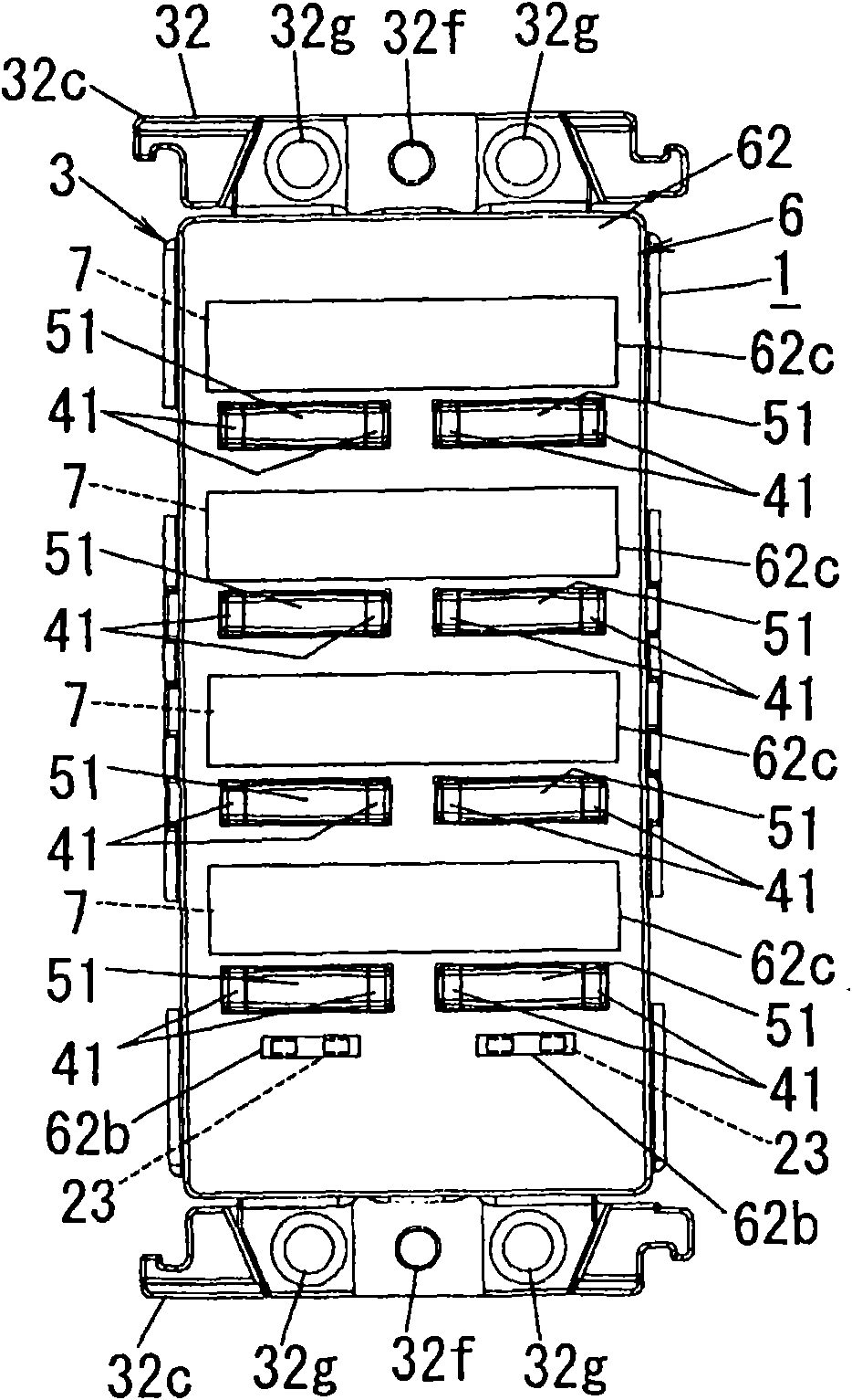
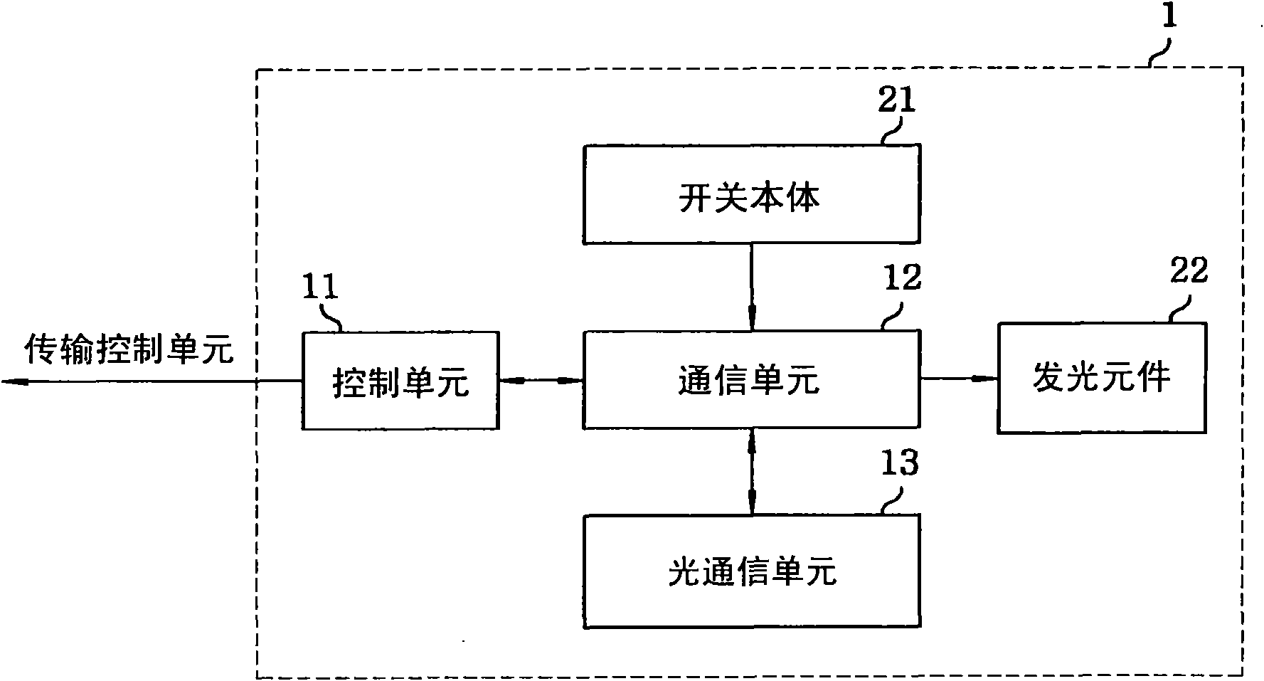
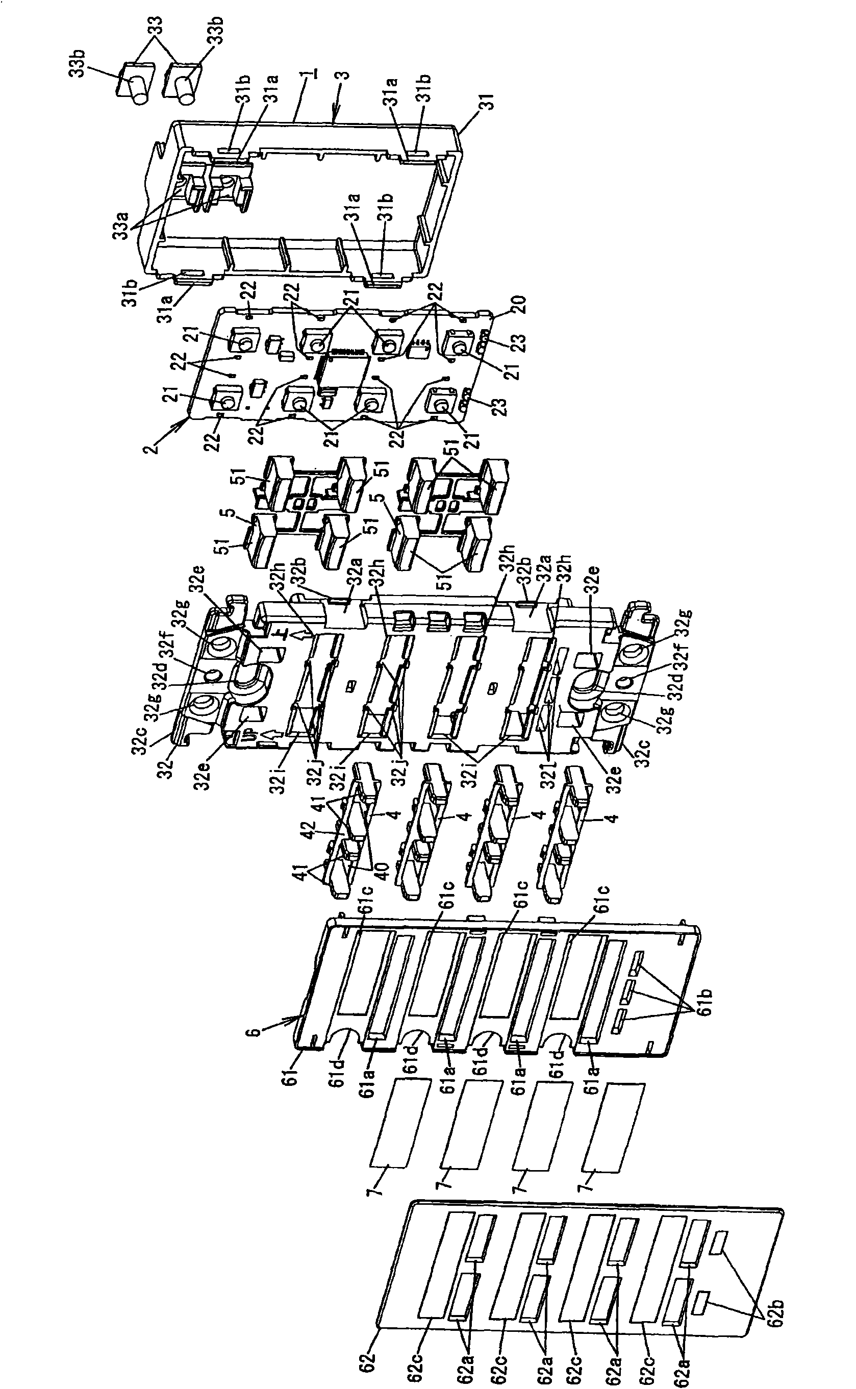
[0083] This example points to the previously referenced Figure 28 and 29A The operation terminal 1 connected to the signal line Ls of the remote monitoring system described in 29C. Such as Figures 1 to 4 As shown, the operation terminal 1 includes: a communication unit 11, which is connected to the signal line Ls, and is used to receive the transmission signal Vs or send the interruption signal Vi and monitor data; eight switch bodies 21 ( figure 2 Only one of them is shown in the figure), which are respectively formed by button switches and assigned individual addresses. Each switch body 21 is combined with a corresponding button handle part 51 as described below to form a control switch; sixteen Light emitting element 22 ( figure 2 Only one of them is shown in the figure), for example, they are respectively formed by light emitting diodes, and for ...


PUM


Abstract

An operation terminal includes a communication unit; an operation terminal control unit; a plurality of on-period light-emitting units provided in a one-to-one correspondence to the control switches and controlled by the operation terminal control unit; a plurality of off-period light-emitting units provided in a one-to-one correspondence to the control switches and controlled by the operation terminal control unit to emit light when the load associated with the corresponding one of the control switches by relational data is in an off-state; and a housing. At least one half of the control switches are arranged one above another in a vertical direction and each of the on-period light-emitting units is arranged in such a fashion as to transversely interpose the corresponding one of the control switches between itself and the corresponding one of the off-period light-emitting units when seen from the front side.

Description

technical field [0001] The invention relates to an operation terminal used in a remote monitoring system. Background technique [0002] Generally, there is provided a remote monitoring system using time division multiplexed signals (for example, see Japanese Patent Laid-Open No. 11-008950, Japanese Patent Laid-Open No. 5-300575, and Japanese Patent Laid-Open No. 2001-086577). Figure 28 Such a remote monitoring system is schematically illustrated in . [0003] The remote monitoring system includes a transmission control unit CU, a plurality of ( Figure 28 In two) operation terminal 1 and multiple ( Figure 28 Two in the middle) control the terminal RU. The operation terminal 1 and the control terminal RU are connected to the transmission control unit CU via a two-wire signal line Ls. [0004] Each operation terminal 1 is provided with at least one control switch ( Figure 28 In the center are four control switches) having a button handle portion 51 pressed and operated by ...

Claims


Application Information

Patent Timeline
Patent Type & Authority Applications(China)
IPC IPC(8): G05B19/04G05B23/00
Inventor 川又基嗣吉村祐一
Owner PANASONIC CORP
Features
  • R&D
  • Intellectual Property
  • Life Sciences
  • Materials
  • Tech Scout
  • Unparalleled Data Quality
  • Higher Quality Content
  • 60% Fewer Hallucinations
Learn More