
Method and device for fluorescent lamp two-wire system dimming control
A technology of dimming control and dimming control signal, which is applied in the field of triac dimming control device and two-wire dimming control of fluorescent lamps, which can solve the problems of large total current harmonic distortion and reduce current harmonic interference. Effect
Patent Information
- Authority / Receiving Office
- CN · China
- Patent Type
- Applications(China)
- Current Assignee / Owner
- Publication Date
- 2009-10-28
- Estimated Expiration
- Not applicable · inactive patent
Smart Images
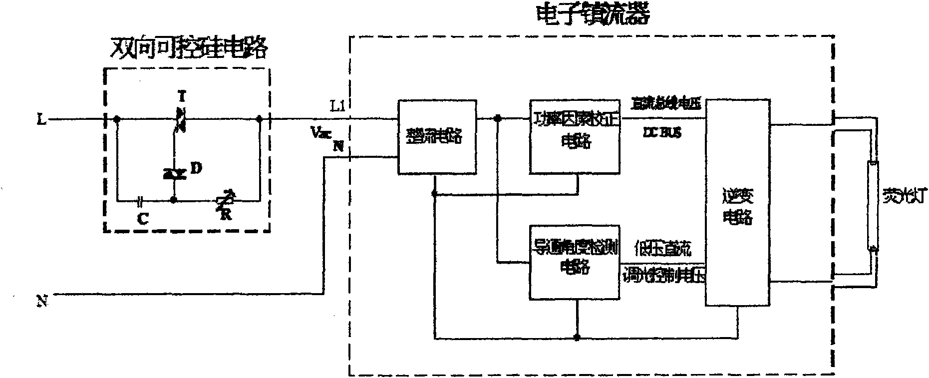
Figure 1 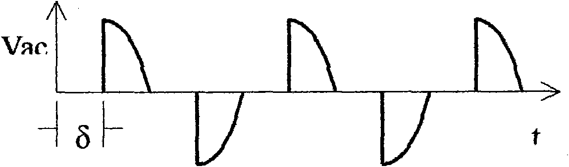
Figure 2 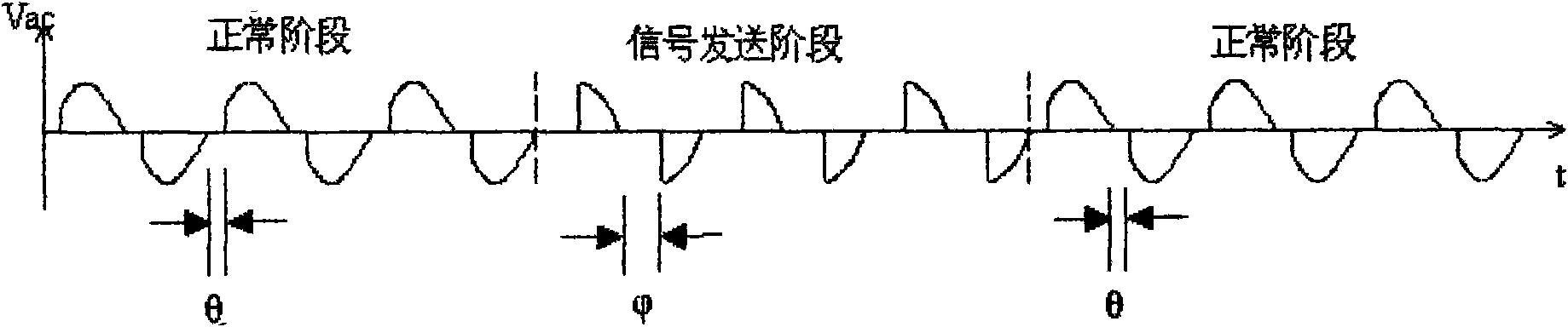
Figure 3
Abstract
Description
Technical field
[0001] The patent of the invention relates to the dimming control technology of fluorescent lamps with electronic ballasts, in particular to a two-wire dimming control method for fluorescent lamps and a bidirectional thyristor dimming control device.
Background technique
[0002] At present, among the light sources for indoor lighting, incandescent lamps have been gradually eliminated due to their low luminous efficiency, high power consumption, and short lifespan. With the development of new materials, new structures, new design theories and manufacturing processes, the comprehensive performance of fluorescent lamps has been greatly improved. With the continuous development of energy-saving and high-efficiency technical advantages, fluorescent lamps have become the main light source for architectural lighting.
[0003] Electronic ballasts for dimmable fluorescent lamps have obvious power-saving effects, and have been rapidly developed and applied in rec...
Examples
Embodiment Construction
[0058] see Figure 4 , the fluorescent lamp two-wire dimming control device of the present invention is formed by connecting the user dimming control terminal 1 and the electronic ballast terminal 2 through a single-phase AC transmission line L1.
[0059] The dimming control signal input circuit 6 is formed by the first microprocessor MCU1 in the user dimming control terminal 1, and the signal output terminal of the dimming control signal input circuit 6 is connected to the impedance switching circuit 4, and the resistance R1 in the impedance switching circuit 4 and The bidirectional thyristor circuit 3 is connected, and constitutes a phase shifting circuit in the bidirectional thyristor circuit 3 (by Figure 4 A part of the phase-shift capacitor C, fixed phase-shift resistor R1, and the first transistor bias resistor R2). The general-purpose input / output port of the first microprocessor MCU1 is connected with the user dimming interface device 13 (referring to Figure 5 ), t...