Electromechanical and solid-state AC relay with reduced arcing

a technology of arcing and arcing, applied in the field of alternating-current (ac) relays, can solve the problems of large electromagnetic interference (emi), difficult to turn the emr on and off at the zero-crossing of the ac current, and more complex alternating-current relays

Inactive Publication Date: 2010-02-09
PERICOM TECH
View PDF13 Cites 20 Cited by
  • Summary
  • Abstract
  • Description
  • Claims
  • Application Information

AI Technical Summary

Benefits of technology

[0022]The solid state relay (SSR) is a type of switch component with no moving parts, having all solid-state electric parts. The SSR uses the switching characteristic of a bidirectional thrysistor to turn on and off currents without mechanical contacts that physically touch and spark. An AC solid-state relay can use a zero-crossing trigger, producing little EMI interference, and can be used safely for computer output interface.

Problems solved by technology

While simple direct current (DC) relays are common, alternating-current (AC) relays may be somewhat more complex since the AC current switches direction.
However, EMR's have some drawbacks.
When AC current is used, it is difficult to turn the EMR on and off at the zero-crossing of the AC current, when the AC current switches direction.
EMR's also have a large electromagnetic interference (EMI).
The stochastic operation time causes the EMR to be incapable of turning on or turning off at exactly the load's AC zero crossing.
This surge current creates interference in the electrical grid system, producing an inextricable EMI problem for the electromagnetic relay.
An electric spark (arc) appears, and the arc discharge creates electrical wear.
This 1-volt drop through the SCR is a serious problem, especially for high-power control applications.
Simply combining an electromechanical EMR relay with a solid-state relay (SSR) would likely produce the disadvantages of both.
The combined device could have low reliability due to arcing of the EMR, and have the voltage-drop problem of the SSR, along with a high cost.

Method used


Image

  • Electromechanical and solid-state AC relay with reduced arcing
  • Electromechanical and solid-state AC relay with reduced arcing
  • Electromechanical and solid-state AC relay with reduced arcing

Examples


Embodiment Construction

[0017]The present invention relates to an improvement in AC relays. The following description is presented to enable one of ordinary skill in the art to make and use the invention as provided in the context of a particular application and its requirements. Various modifications to the preferred embodiment will be apparent to those with skill in the art, and the general principles defined herein may be applied to other embodiments. Therefore, the present invention is not intended to be limited to the particular embodiments shown and described, but is to be accorded the widest scope consistent with the principles and novel features herein disclosed.

[0018]The inventors have realized the desirability of a solution to the technical problem of the low reliability of electromechanical relays caused by arcing of the mechanical contacts, and the 1-volt drop of the solid-state relay.

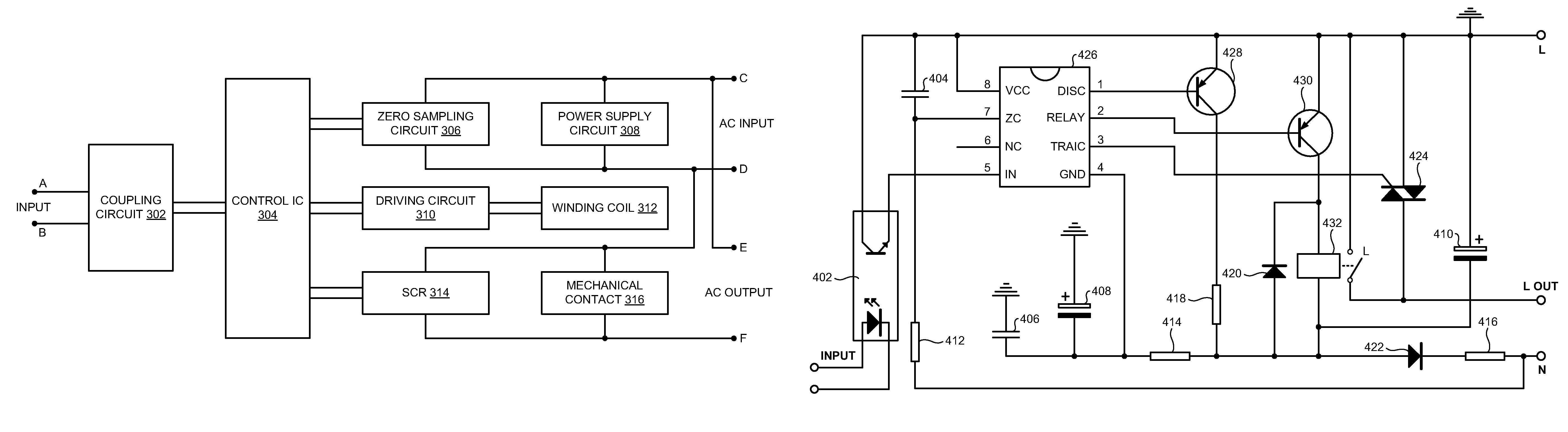
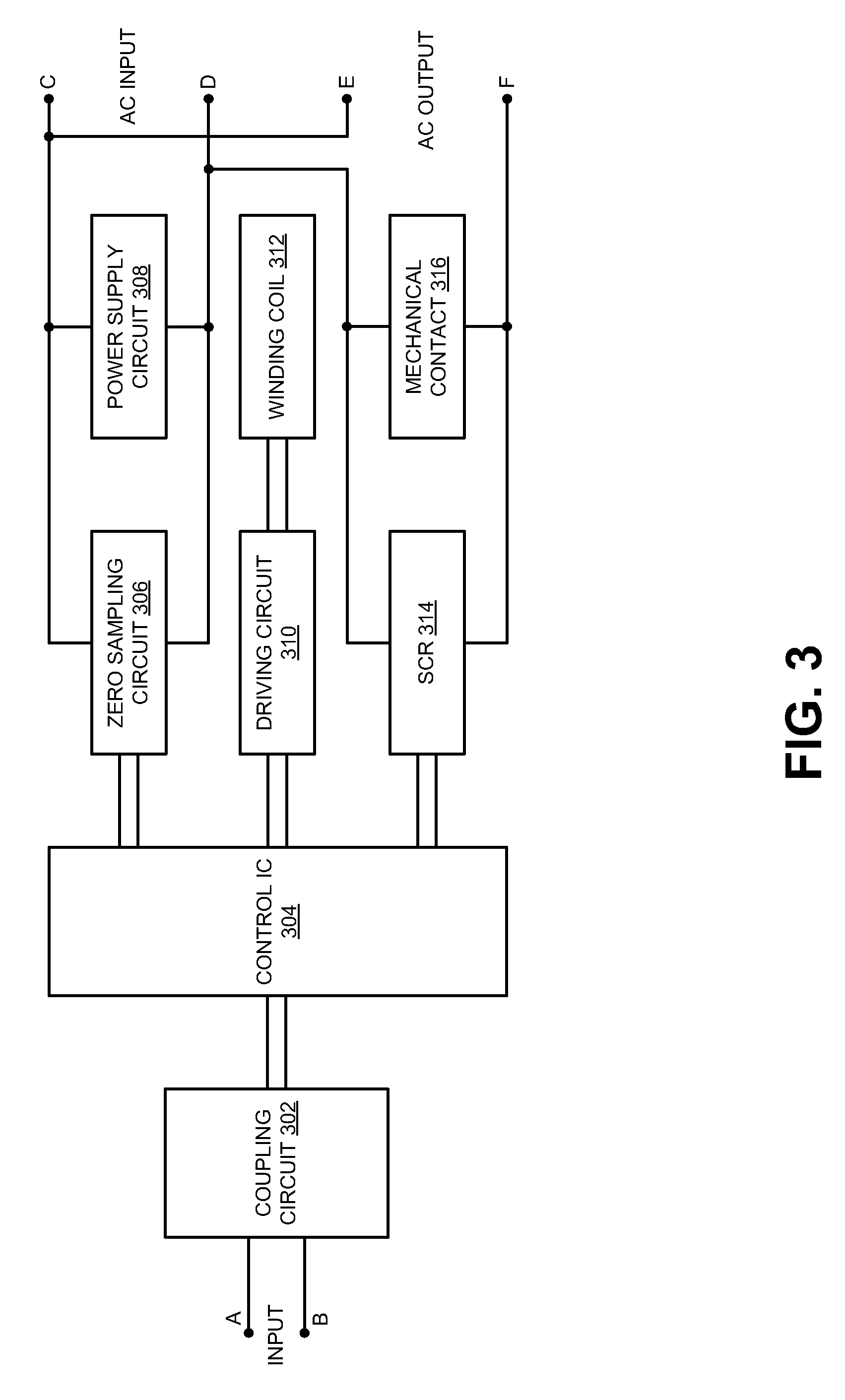
[0019]The electromagnetic relay usually has an iron core, a winding coil, an iron armature, a movable spring wi...


PUM


Abstract

An electromechanical / solid-state AC relay has an electromechanical winding coil that moves an armature to force mechanical contacts to open or close. Electrical arcing across the mechanical contacts that occur as the contacts are opening or closing can damage and severely reduce the lifetime of the relay. Contact arcing is prevented by pulsing a triac on for a short period of time just before and after the mechanical contacts make or break contact. The triac limits the voltage difference across the mechanical contacts to less than one volt to prevent arcing. The triac is turned off after the mechanical contacts finish moving, reducing the heating and average power through the triac. A zero-sampling circuit that detects when the AC input voltage switches across 0 volts and activates a control integrated circuit to switch on the triac during zero-crossings to minimize power surges.

Description

RELATED APPLICATION[0001]This application claims the benefit under 35 USC § 119 of the co-pending application for “AC Relay”, China App. No. 200620045110.0, filed Aug. 25, 2006.FIELD OF THE INVENTION[0002]This invention relates to alternating-current (AC) relays, and more particularly to AC relays with both mechanical and solid-state contacts.BACKGROUND OF THE INVENTION[0003]A relay is a type of electronic control device that often used as an automatic control circuit. It has a control system (also known as the input circuit) and a controlled system (also known as the output circuit). A smaller current in the control system can control a larger current of the controlled system using such an “Automatic Switch.”[0004]While simple direct current (DC) relays are common, alternating-current (AC) relays may be somewhat more complex since the AC current switches direction. However, many commercial appliances use AC and thus could benefit from an AC relay to control the AC current that powe...

Claims


Application Information

Patent Timeline
Patent Type & Authority Patents(United States)
IPC IPC(8): H02H3/00H02H7/00
CPCH01H9/542Y10T307/911
Inventor YAO, LICHEN, SHU PENGWEI, YONG
Owner PERICOM TECH
Why Eureka
Try Eureka