Two terminal arc suppressor

a technology of arc suppressor and terminal, which is applied in the direction of emergency protective devices, electrical equipment, emergency protective circuit arrangements, etc., can solve the problems of increased maintenance costs, equipment failure, unnecessary down time on production lines, etc., and achieve the effect of greatly strengthening the microweld connection

Active Publication Date: 2013-12-31
ARC SUPPRESSION TECH LLC
View PDF315 Cites 21 Cited by
  • Summary
  • Abstract
  • Description
  • Claims
  • Application Information

AI Technical Summary

Benefits of technology

[0030]The present invention provides an arc suppressor for switch contacts coupling a voltage source to a load where the arc suppressor comprises a pair of terminals adapted to be connected across a set of switch, relay or contactor contacts to be protected and where a solid state triggerable switch is connected between the pair of terminals. A triggering circuit is operatively coupled to the solid state triggerable switch and operative when the switch contacts move from a closed state to an open for driving the solid state triggerable switch into a conductive state to short out the switch contacts and further including a pinch-off circuit that is coupled to the triggering circuit for controlling the length of time that the solid state triggerable switch remains in its conductive state following movement of the switch contacts from the closed state to the open state.

Problems solved by technology

This metal migration pits out and destroys the contact surfaces over time, eventually leading to equipment failure.
This type of contact failure results in increased maintenance costs, unnecessary down time on production lines, higher frequency of product failures and many other issues that cost companies time, money and reputations.
Current solutions in use today address contact arcing with modestly effective devices, including Solid State Relays (SSR's), Hybrid Power Relays (HPR's) which are custom-designed and expensive, and RC snubber circuits, which barely mitigate the problem.
Contact current arc suppression technology is either expensive and short-lived or durable, but risky at the product's end-of-life.
Environmental and health concerns, over the years, have lead to the replacement of highly durable mercury displacement relays (MDR) with electromechanical relays and contactors, leaving both industry and products vulnerable to the negative effects of contact arcing.
There are various undesirable effects of using the current technology, namely, environmental risks associated with disposal, high costs of replacement, and catastrophic end-of-life that needs to be proactively mitigated.
However, these same switches, relays or contactors decay more rapidly when carrying a load current.
The inevitable end-of-life (EOL) event for any switch, relay or contactor is failure.
But, the EOL failure mode of an MDR is typically catastrophic, with an explosion of its mercury-filled contact chamber and the release of highly toxic mercury vapors into its operating environment.
Needless to say, this type of failure is especially undesirable when the MDR is operating in equipment that is used to process or prepare food.
The law requires proper disposal of these MDR's, a step often overlooked, to the detriment of the environment.
Due to ignorance, equipment containing MDR's is typically buried in landfills that may be close to populated communities.
However, coil de-activation may not be as responsive in opening the contact in the same time frame.
The contact spring force is, sometimes, not strong enough to achieve the separation because of this micro-welding effect.
This type of contact failure is reason enough to invalidate the use of the energization status of the relay or contactor coil to assume existence of a suppressible arc in any contact arc suppression solution.
When switches, relays or contactors fail, serious fire hazard conditions are often present.
Full arc suppression of mechanical switches, relays or contacts with current state-of-the-art technology is not achievable for mechanical contacts.
It is not required for solid state switches or hybrid power relays; however, those devices are expensive and not universal.
An arc suppressor whose arc suppression element is “always on” during the closed contact state is dangerous.
They must be inherently safe and, if not designed correctly, the arc suppressor becomes a fire hazard and a liability.
Arc suppressors of the prior art with three or more wires are neither optimal nor inherently safe because they rely on coil and power to decide when to suppress the arc.

Method used


Image

  • Two terminal arc suppressor
  • Two terminal arc suppressor
  • Two terminal arc suppressor

Examples


Embodiment Construction

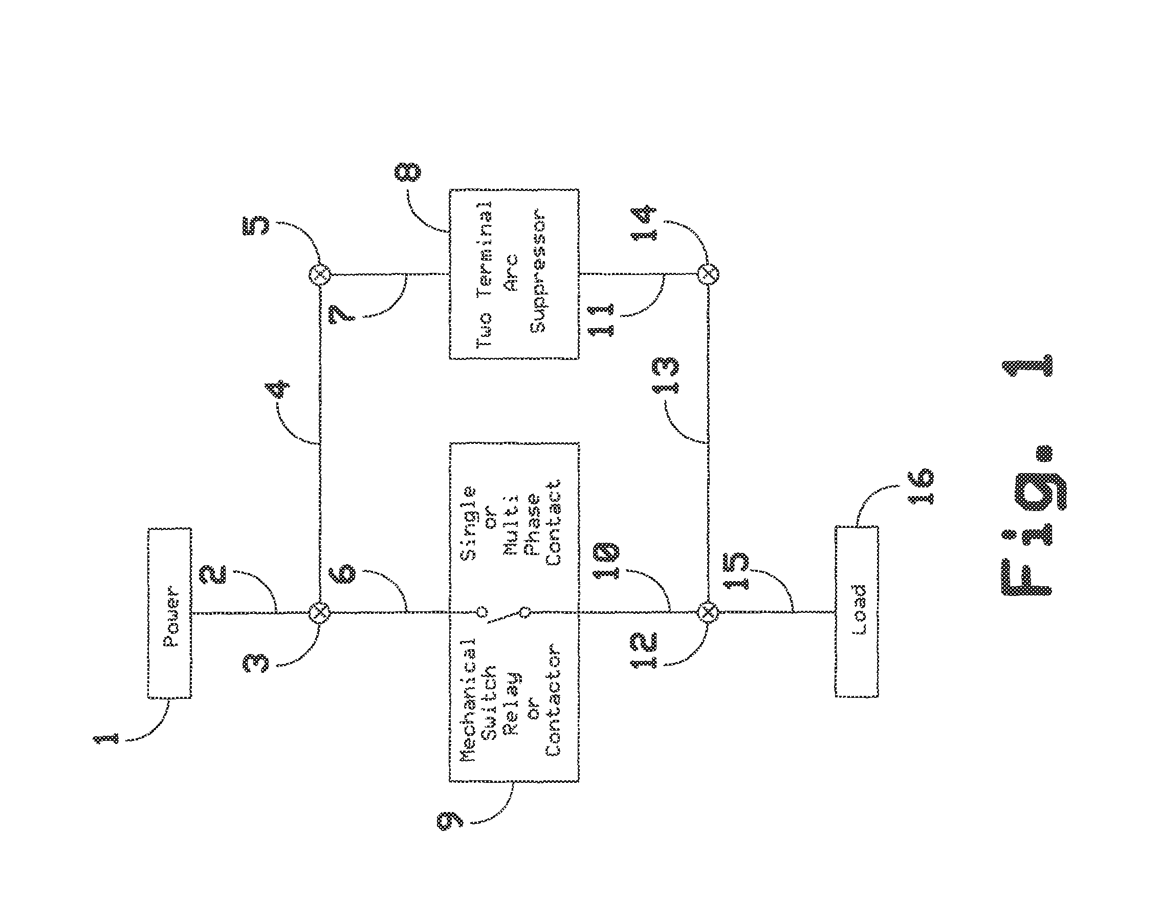
[0040]The following detailed description relates to a two terminal arc suppressor directed toward extending the life of switches, relays and contactors used to switch either an alternating current (AC) or a direct current (DC) source to a load.

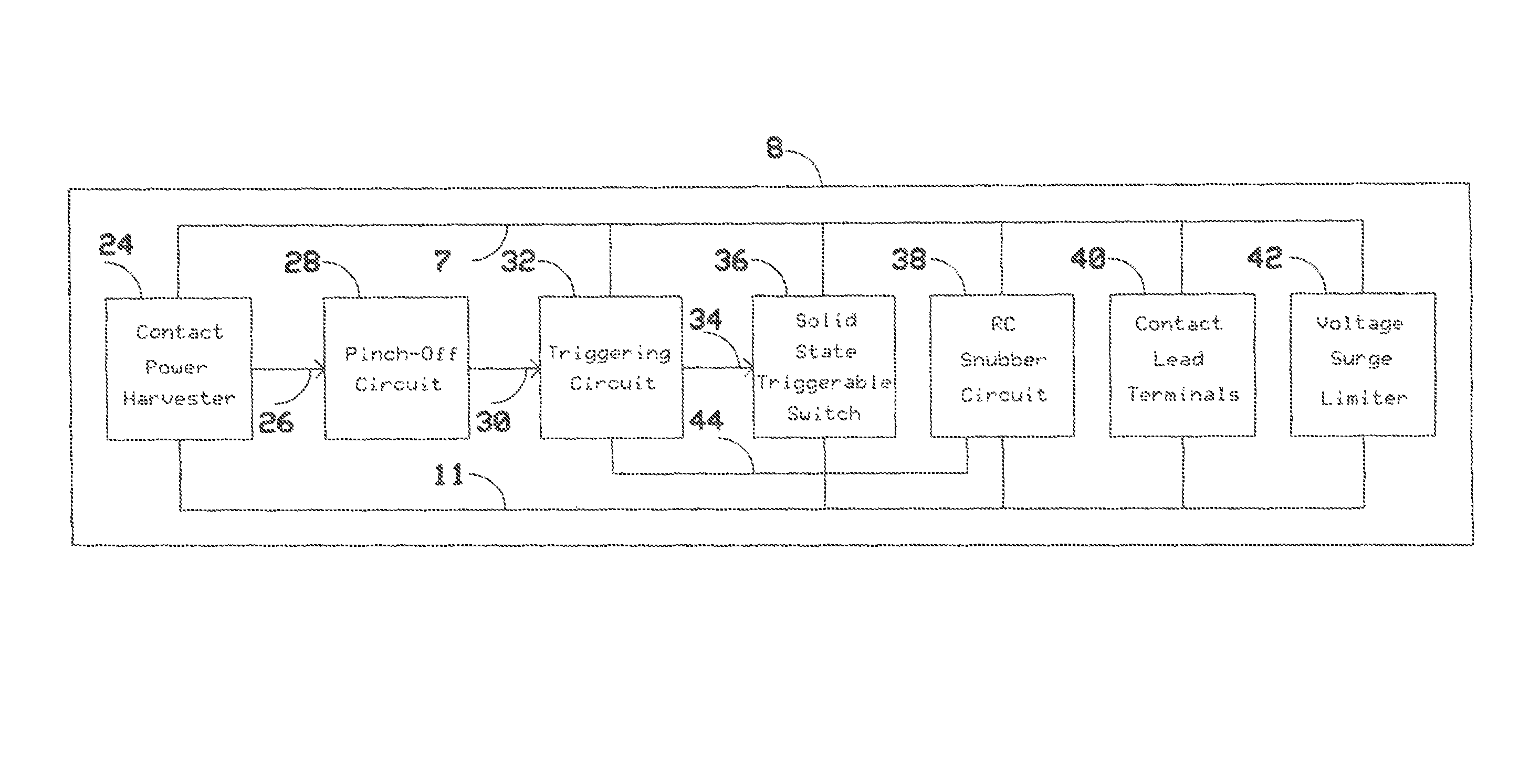
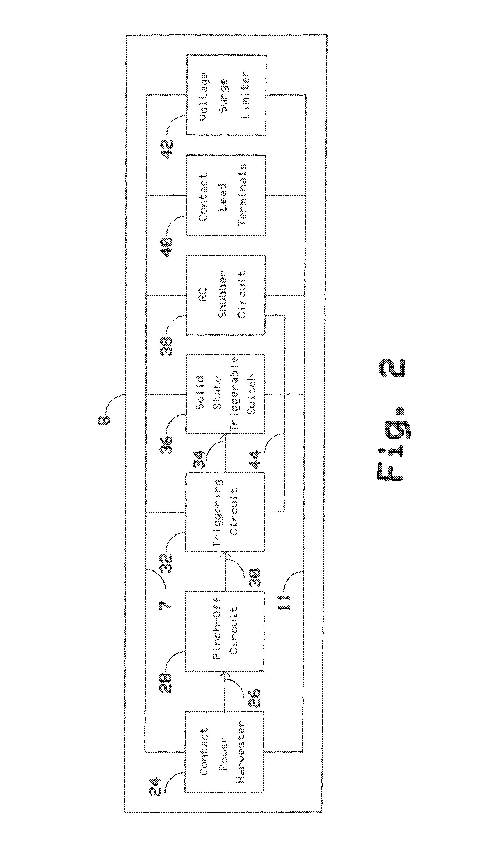
[0041]The following detailed description includes discussion of a two terminal arc suppressor connected to a mechanical switch, relay or contactor. Additionally, elements of a two terminal arc suppressor discussed including a contact power harvester, a pinch-off circuit, a triggering circuit, a solid state triggerable switch, an RC snubber circuit, contact lead terminals, a voltage surge limiter and a timing diagram is included.

[0042]The present invention can be readily understood from a discussion of FIGS. 1 through 6.

[0043]FIG. 1 illustrates generally an example of a system including a two terminal arc suppressor 8. In an example, an AC or a DC power source 1 is connected via wire 2 to the terminal 3 of a mechanical switch, relay or contacto...


PUM


Abstract

A two terminal arc suppressor for protecting switch, relay or contactor contacts and the like comprises a two terminal module adapted to be attached in parallel with the contacts to be protected and including a circuit for deriving an operating voltage upon the transitioning of the switch, relay or contactor contacts from a closed to an open disposition, the power being rectified and the resulting DC signal used to trigger a power triac switch via an optoisolator circuit whereby arc suppression pulses are generated for short predetermined intervals only at a transition of the mechanical switch, relay or contactor contacts from an closed to an open transition and, again, at an open to a close transition during contact bounce conditions.

Description

TECHNICAL FIELD[0001]This invention relates generally to the field of arc suppressors and more specifically to the area of two terminal arc suppressors used to prevent the contact points of switches, relays or contactors from suffering premature failures due to the deleterious effects of contact current arcing during the contact closed to contact open transition and during the contact open to contact closed transitions. More particularly, the present invention relates to a device for extending contact life without requiring any external control wires, power wires or any other wires other than the two contact terminal wires that are used to connect the arc suppressor invention to the two contact points between which the arc is to be suppressed.BACKGROUND[0002]Every time an electrical heater, lamp or motor is turned on or off, using a single or multiphase switch, relay or contactor, an electrical arc occurs between the two contact points where the single or multiphase power connects t...

Claims


Application Information

Patent Timeline
Patent Type & Authority Patents(United States)
IPC IPC(8): H02H3/00
CPCH01H9/542H01H9/30H01H9/547H01H89/00
Inventor HENKE, REINHOLD
Owner ARC SUPPRESSION TECH LLC
Why Eureka
Try Eureka