System for and method of projection weld-bonding workpieces

A technology for protruding parts and workpieces, which is applied in the welding-adhesive workpiece system and field of protruding parts, and can solve problems such as low total strength

Inactive Publication Date: 2009-11-18
GM GLOBAL TECH OPERATIONS LLC
View PDF1 Cites 21 Cited by
  • Summary
  • Abstract
  • Description
  • Claims
  • Application Information

AI Technical Summary

Problems solved by technology

However, it should also be known that this method of joining generally yields lower overall strength compared to welded joints

Method used


Image

  • System for and method of projection weld-bonding workpieces
  • System for and method of projection weld-bonding workpieces
  • System for and method of projection weld-bonding workpieces

Examples


Embodiment Construction

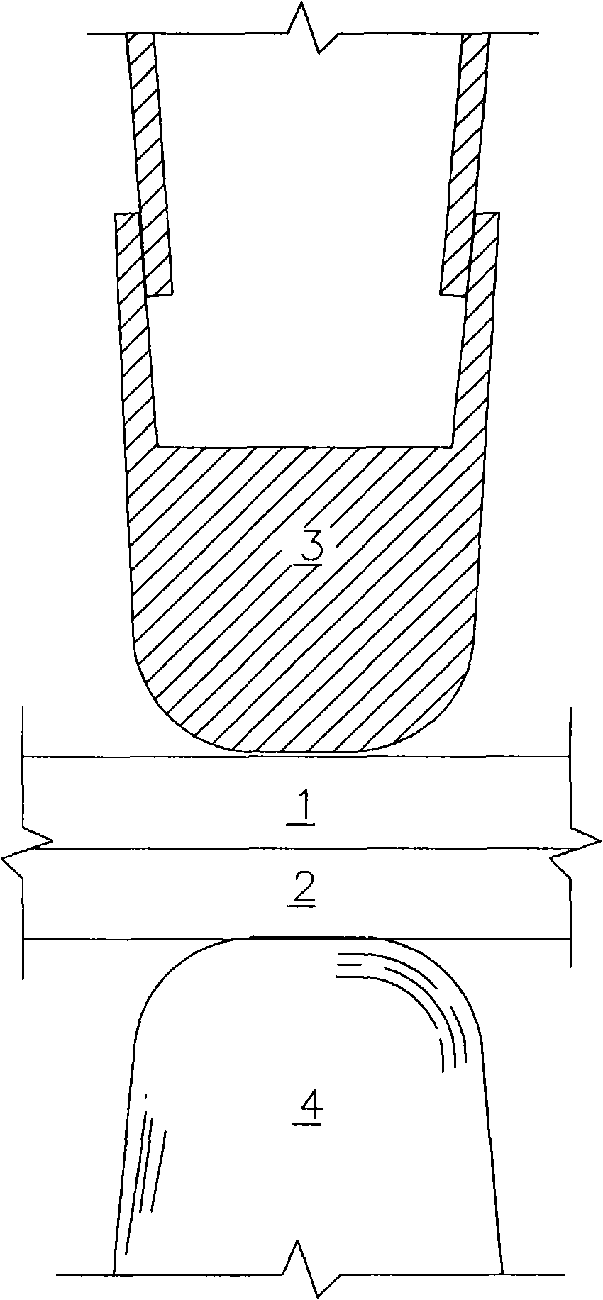
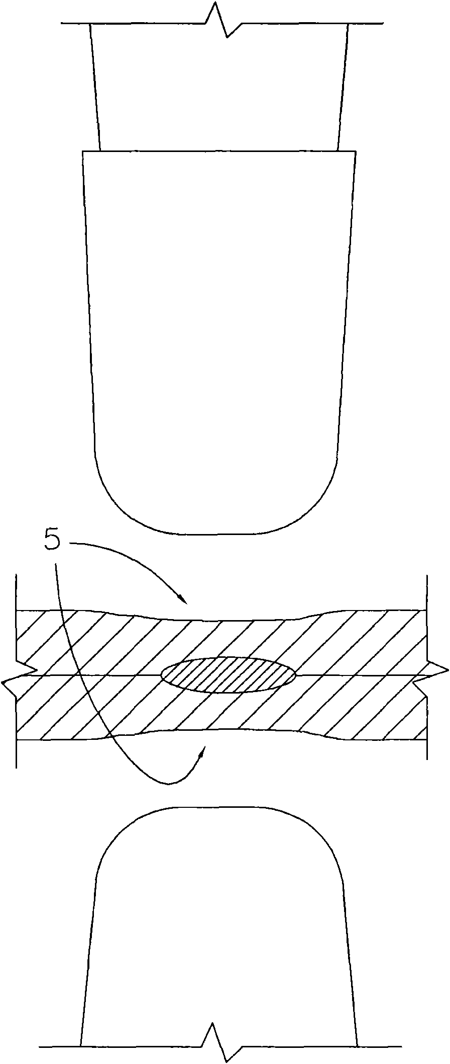
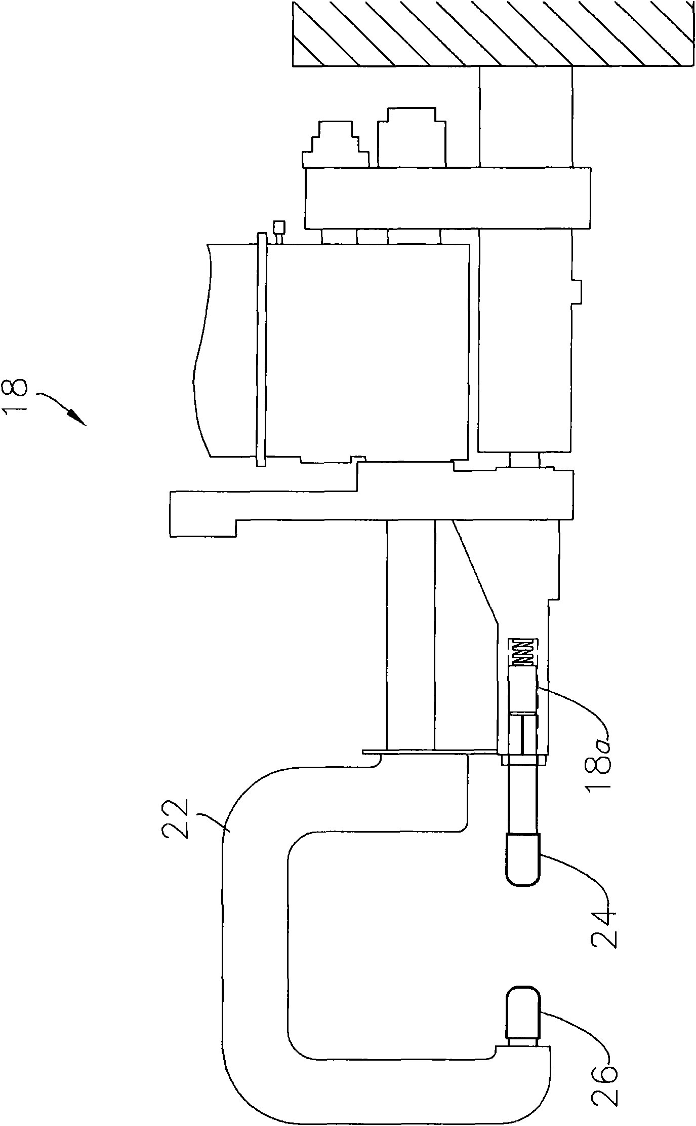
[0016] The present invention relates to a system 10 ( Figure 2-13b ) and methods. The system 10 of the present invention is configured to produce welds 12 that are respectively invisible to the exterior of the constructed workpiece assembly (compare FIGS. 1a and 2b ). That is, no outer surface deformations or irregularities, such as surface dimples, are formed during the inventive resistance welding process described herein. It will be appreciated that the present invention thus increases the aesthetic appeal and reduces the manufacturing costs associated with the assembled product. The present invention is suitable for use with conventional resistance spot welding equipment (such as in Figure 1b 18), and requires no additional welding equipment and / or modifications.

[0017] In the illustrated embodiment, two workpieces 14, 16 of equal thickness are shown; however, by modifying or applying the teachings of system 10 as desired, the system 10 of the present invention can be...


PUM

PropertyMeasurementUnit
diameteraaaaaaaaaa

Abstract

A system for and method of projection weld-bonding a plurality of workpieces, includes the steps of securing at least one adhesive layer having a plurality of projections embedded therein intermediate the workpieces, and engaging the workpieces with a resistance welding apparatus such that only the projections fuse to form the weld pool, and the layer cures to form an adhesive seal around the welds, together the adhesive layer and projections cooperatively forming a reinforced joint.

Description

[0001] Cross References to Related Applications [0001] A U.S. nonprovisional patent application related to this application claims priority to pending U.S. nonprovisional application No. 11 / 937518, filed November 9, 2007, entitled "SYSTEM FOR AND METHOD OF PRODUCTING INVISIBLE PROJECTION WELDS," and This application is a continuation-in-part of the above application. technical field [0002] The present invention relates to resistance welding systems and methods of bonding, and more particularly to resistance welding systems and methods for welding-bonding a plurality of workpieces using protrusions embedded within an adhesive layer. Background technique [0003] Resistance spot welding (eg, conventional spot or seam welding) remains the most common method of joining metal workpieces in a variety of industries, including automotive manufacturing and construction. In this method, the workpieces 1 , 2 are usually secured in a fixed situation and then joined by two electrod...

Claims


Application Information

Patent Timeline
Patent Type & Authority Applications(China)
IPC IPC(8): B23K11/08B23K11/16B23K11/34B23K11/06B23K11/36
CPCB23K2203/04B23K2201/18B23K11/115B23K11/14B23K11/20B23K2203/20B23K2101/18B23K2103/04B23K2103/20Y10T428/24479
Inventor A·D·哈哈列夫
Owner GM GLOBAL TECH OPERATIONS LLC
Why Eureka
Try Eureka