
Golf putter heads and manufacture method thereof

A technology of putter head and golf, applied to golf balls, golf clubs, rackets, etc.

Active Publication Date: 2013-01-16
KARSTEN MFG CORP
View PDF4 Cites 0 Cited by
  • Summary
  • Abstract
  • Description
  • Claims
  • Application Information

AI Technical Summary

Problems solved by technology

Since increasing the MOI of a golf club head increases resistance to undesired golf club head twist during off-center hits, individual golf club head performance can be affected by MOI

Method used


Image

  • Golf putter heads and manufacture method thereof
  • Golf putter heads and manufacture method thereof
  • Golf putter heads and manufacture method thereof

Examples


Embodiment Construction

[0023] Methods, apparatus, and articles of manufacture relating to golf club heads are generally described herein. The methods of manufacture, apparatus and articles described herein are not limited thereto.

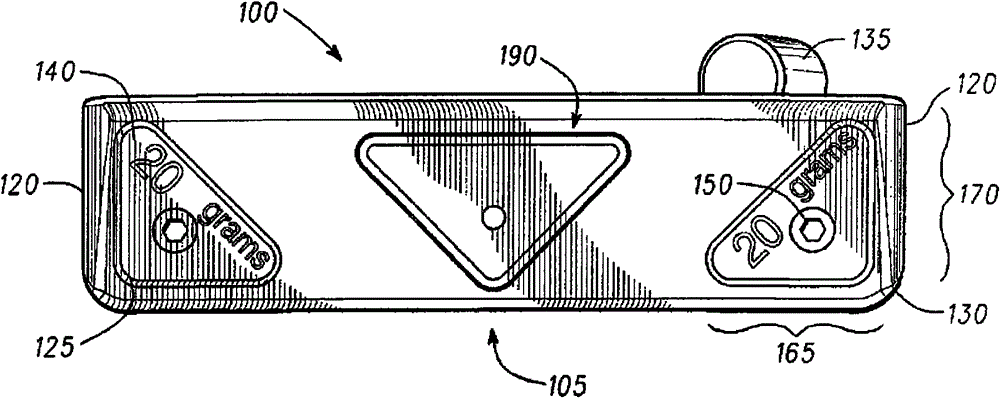
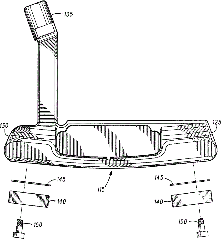
[0024] exist Figures 1 to 8 In an example, a golf putter head 100 may include a sole 105, a face 110 for striking a golf ball (not shown), a rear 115, and two side portions 120, wherein the face 110 is also referred to herein as a striking face . Golf putter head 100 may also include toe portion 125 and heel portion 130 . Golf putter head 100 may further include a hosel portion 135 adapted to receive an end of a shaft (not shown). In one example, golf putter head 100 may be fabricated from steel or steel-based materials through a casting process, a forging process, a combination of the two, or other suitable manufacturing processes.

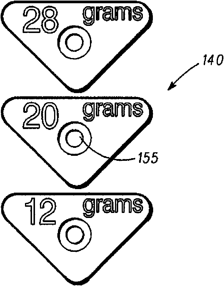
[0025] refer to figure 1 and 2 For example, the golf putter head 100 can be provided with a plurality of detachable weights 140 , ...


PUM


Abstract

Embodiments of golf clubs, golf club heads and removable golf club weights are generally described herein. According to certain embodiments, an example golf club head comprises a face for striking a golf ball, a backside portion, a sole portion, and one or more removable weights. According to such embodiments, the example golf club head may further comprise a vibration damping composition disposed between the removable weights and the golf club head.

Description

[0001] priority claim [0002] This application claims priority to US Patent Application Serial No. 12 / 101,101, filed April 10,2008. technical field [0003] The present disclosure relates generally to golf equipment, and more particularly to golf putter heads, methods of making golf putter heads, and removable weights for use with golf putter heads. Background technique [0004] The moment of inertia (MOI) produced by a golf club head is affected by the weight and distribution of weight located in the golf club head, including the putter head. Since increasing the MOI of a golf club head increases resistance to undesired golf club head torsion during off-center hits, an individual's performance with a golf club head can be affected by the MOI. Therefore, increasing the MOI of the golf club head can provide greater forgiveness during off-center hits. Thus, increasing the MOI of a golf club head is generally desirable, and to some extent (and to some extent) also desirab...

Claims


Application Information

Patent Timeline
Patent Type & Authority Patents(China)
IPC IPC(8): A63B53/06
CPCA63B53/0487A63B2053/0433A63B59/0092A63B2053/0491A63B2209/08A63B60/54Y10T29/49Y10T29/49963A63B53/0433A63B60/02A63B53/065A63B53/04
Inventor 戴维·D·琼斯理查德·R·桑切斯布拉德利·D·施韦格特迈克尔·R·尼科莱特
Owner KARSTEN MFG CORP
Learn More