Safe ventilated electric connector

An electrical connector and ventilated technology, applied in the field of ventilated electrical connectors, can solve problems such as top opening, seal failure, fixed connection damage, etc., and achieve the effects of easy use, guaranteed mating in place, and small vibration interference

Inactive Publication Date: 2012-05-09
CHINA AVIATION OPTICAL-ELECTRICAL TECH CO LTD
View PDF4 Cites 0 Cited by
  • Summary
  • Abstract
  • Description
  • Claims
  • Application Information

AI Technical Summary

Problems solved by technology

However, in case of accidents, such as the O-ring on the air needle contact is missing or aging or damaged, the seal between the air needle contact and the air hole contact will fail, and the high-pressure gas will flow from the air needle The joint between the contact piece and the air hole contact piece leaks, and the leaked high-pressure gas will accumulate high pressure in the gap between the mating surfaces of the plug and socket. Since the shell of the plug and socket is sealed, it is easy to make the connection state Plugs and sockets tend to be pushed apart by high-pressure gas
Especially for the insulator in the socket and the socket contact, because it is sealed and fixed in the connector by conventional technology, its high pressure resistance is much lower than that of the locking device on the connector, which is easy to cause leakage of high pressure The gas pushes the socket contact and the insulator out of the connector shell gradually. Due to the high-pressure impact force of the leaked high-pressure gas up to 10000N, after being subjected to multiple high-pressure gas impacts, the socket contact and the insulator are in contact with the shell shell. The fixed connection between them is completely destroyed, causing the socket contacts and insulators to be ejected from the socket housing driven by high-pressure gas, and the ejected objects will have high penetration, which is harmful to the operator. and equipment safety, causing great harm and forming a major safety hazard

Method used


Image

  • Safe ventilated electric connector
  • Safe ventilated electric connector
  • Safe ventilated electric connector

Examples


Embodiment 1

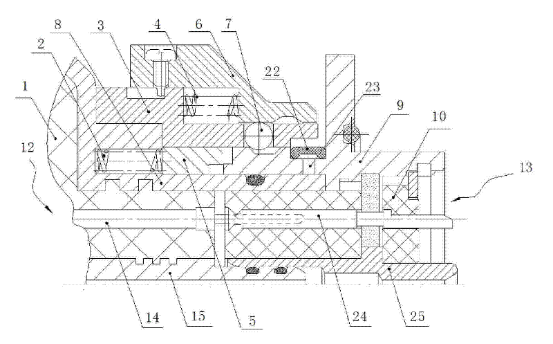
[0019] Embodiment one: if figure 1 , figure 2 , Figure 4 As shown, the safety ventilated electrical connector of the present invention includes a plug 12 and a socket 13 , and the insertion end of the plug 12 is provided with an opening for inserting the insertion end of the socket 13 . The plug 12 includes a plug housing 3, the plug-in end opening of the plug 12 is arranged at one end of the plug housing 3, the spline housing 8 is fixed in the plug housing 3, and the inner wall of the spline housing 8 is provided with a The extended spline, the spline housing 8 is fixed with a plug insulator 1, and a contact is inserted in the plug insulator 1, and the contact includes a high-pressure gas needle contact 15 located in the center of the connector and a high-voltage gas needle contact 15 located at the center of the connector. 14 around the electrical pin contacts. The socket 13 includes a socket housing 9 and a socket insulator 10 fixed therein. The socket housing 9 is pro...

Embodiment 2

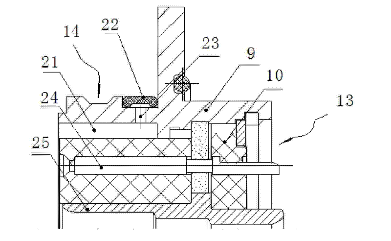
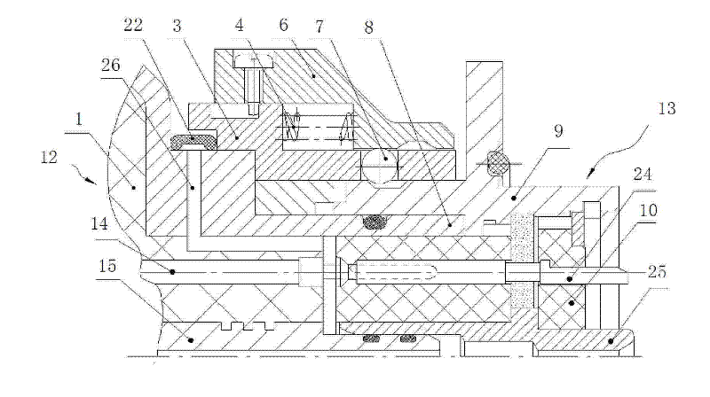
[0023] Embodiment two: if image 3 , Figure 4 As shown, the difference between the second embodiment and the first embodiment is that the plug 12 is provided with more than one connecting mating surface of the insulator and the channel 26 on the outer wall of the plug 12 to form a pressure relief channel. The front section of the pressure relief channel It is set axially between the spline housing 8 and the insulator 1 , its rear end is radially set on the spline housing 8 , and the annular rubber pad 22 is packaged on the outer opening of the channel 26 .


PUM


Abstract

The invention discloses a safe ventilated electric connector. Locking devices matched mutually are respectively arranged on the outer shells of a plug and a socket, and an electric contact and a high-pressure air circuit contact which are plugged and matched mutually are respectively arranged in the outer shells of the plug and the socket. At least one pressure relief passage communicated with the outside of the connector is arranged on the plug or the socket of the connector at the plug matching surface, and an overpressure relief rubber pad is arranged at the outlet of each pressure relief passage, which is located at the outer wall of the outer shell of the plug or the socket. When the air circuit contact inside the connector leaks, leaked high-pressure gas pushes the overpressure relief rubber pad open for release through the pressure relief passage, thereby ensuring the connection stability of the plug and the socket inside the connector, avoiding the serious potential safety hazard that the electric contact is pushed out of the connector as a result of the gathering of the leaked high-pressure gas, and enhancing the safety of the safe ventilated electric connector.

Description

technical field [0001] The invention belongs to the technical field of ventilated electrical connectors, and in particular relates to a ventilated electrical connector provided with a safety protection device. Background technique [0002] In order to prevent the plug and socket of the ventilated electrical connector currently used from being pushed apart by high pressure, it must be fixedly connected by a locking device during use. When the plug and the socket are plugged in, the locking device connects the plug and the socket firmly, the spline housing on the plug is inserted into the ring groove on the socket, and the outer surface of the spline housing of the plug is provided with a ring for connecting with the socket. The O-ring of the groove sealing fit also forms a gap between the mating faces of the plug and the socket relative to each other. The center of the socket and the plug is respectively pierced with an air needle contact and an air hole contact that are mat...

Claims


Application Information

Patent Timeline
Patent Type & Authority Patents(China)
IPC IPC(8): H01R13/533H01R13/639F16K17/02E05B65/00
Inventor 陈继利王鹏
Owner CHINA AVIATION OPTICAL-ELECTRICAL TECH CO LTD
Why Eureka
Try Eureka