Drain device

A technology of falling water head and horizontal tank, which is applied in water supply equipment, indoor sanitary pipeline installations, buildings, etc., and can solve problems such as inconvenience, many components, and easy loss

Inactive Publication Date: 2011-06-08
THANK GOD ENTERPRISE
View PDF0 Cites 0 Cited by
  • Summary
  • Abstract
  • Description
  • Claims
  • Application Information

AI Technical Summary

Problems solved by technology

[0003] There are many kinds of common drain head structures. The most basic structure is to bolt a cover body with holes and grooves on the drainage hole. It is blocked on the cover body, but its disadvantage is that the cover body must be unscrewed to be cleaned, which is extremely inconvenient; therefore, it can be seen that an improved drain head device is generally installed in the drain hole of the sink of the sink, which mainly includes A movable upper cover, a rubber auxiliary cover, and a filter body with a certain capacity. Usually, a space with an outer diameter slightly larger than the drain pipe is provided at the place where the drain pipe connects to the drain hole, and the filter body can be installed in it. , and then sequentially cover the auxiliary cover and the upper cover on the filter body, the upper cover can completely close the drain hole, so that the water in the tank will not be discharged, and the top of the upper cover is equipped with a pull ring, which can provide The user pulls the upper cover open, so that the water flows through the auxiliary cover and the filter body, and then is discharged into the drain pipe through the filter holes of the filter body. As for the rubber auxiliary cover, there is a radial in the center The hollow groove makes the center of the cover form an elastic covering state. Its main function is to provide proper coverage for the drainage holes, prevent the discharge of odors from the drainage pipes, and not hinder the discharge of water. At the same time, it can also provide It has the function of blocking sundries to a certain extent; however, since the components of this type of water drop device are separated from each other, there are many components, which causes inconvenience in installation, cleaning or taking, and is easy to lose

Method used


Image

  • Drain device
  • Drain device
  • Drain device

Examples


Embodiment Construction

[0015] The technical means and effects used by the present invention to achieve the purpose will be described below with reference to the attached drawings, and the embodiments listed in the following drawings are only for auxiliary explanation, so as to facilitate the understanding of the review committee, but the technical means of this case are not Not limited to the listed drawings.

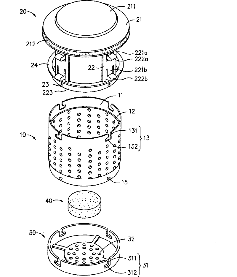
[0016] see figure 1 As shown, the drain head device provided by the present invention includes a body 10 , a top cover assembly 20 and a bottom cover 30 .

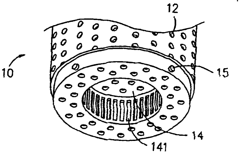
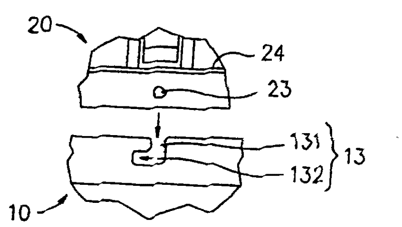
[0017] The main body 10 has an internal space 11, and the main body 10 is provided with a plurality of hollow parts 12 passing through the internal space 11; the top edge of the main body 10 is provided with a slot 13, and the slot 13 is formed by a vertical slot 131, And the horizontal groove 132 that communicates with this vertical groove 131 constitutes, and the top of this vertical groove 131 is to run through this body 10 top; Pleas...


PUM


Abstract

The invention relates to a drain device, which comprises a body, a top cover assembly and a bottom cover. The body is provided with an inner space, and a plurality of permeable parts running through the inner space. The top cover assembly is separably arranged on the top of the body and comprises a top cover and a plurality of connecting pieces. The connecting pieces extend a certain length from the bottom of the top cover. The bottoms of the connecting pieces are connected with each other. Each connecting piece is provided with an upper elastic sheet and a lower elastic sheet. The upper and lower elastic sheets are provided with corresponding convex parts towards the outside of the top cover. The bottom cover is separably arranged on the bottom of the body. A certain space is formed between the bottom cover and the body. The bottom cover is provided with a permeable part. Due to the combination of the components, an outer edge of each convex part protrudes out of the body and an outer side wall of the bottom cover, and can be applied with a force so that the convex part inwards contracts toward the inside of the top cover, and the convex part can be automatically popped up when the external force is eliminated so that the outer edge of the convex part protrudes out of the body and the outer side wall of the bottom cover again.

Description

technical field [0001] The invention relates to a drain head device, especially a drain head device with an integrated structure, which can be quickly disassembled and cleaned, easy to use, and has the functions of drainage, filtration and sanitation, and is suitable for the application and manufacturing related fields of the drain head device . Background technique [0002] Press, the drain head commonly installed on floors, counters, and bathtubs not only provides drainage, but also has a filtering function to prevent hair, vegetable crumbs and other debris from falling directly into the drain pipe and causing blockage. [0003] There are many kinds of common drain head structures. The most basic structure is to bolt a cover body with holes and grooves on the drainage hole. It is blocked on the cover body, but its disadvantage is that the cover body must be unscrewed to be cleaned, which is extremely inconvenient; therefore, it can be seen that an improved drain head devi...

Claims


Application Information

Patent Timeline
Patent Type & Authority Patents(China)
IPC IPC(8): E03C1/282E03C1/26
Inventor 李一君
Owner THANK GOD ENTERPRISE
Why Eureka
Try Eureka