Sucker line device

A suction cup and pipeline technology, which is applied to suction devices, hypodermic injection devices, extraction and pumping systems, etc., can solve problems such as the discomfort of pressure and discomfort in the extraction pipeline, and avoid the probability of air leakage from the machine and the safety of the pipeline. The effect of chaotic and delaying the use of the machine

Pending Publication Date: 2019-03-19
SUNEETEK XIAMEN MEDICAL EQUIP CO LTD
View PDF1 Cites 0 Cited by
  • Summary
  • Abstract
  • Description
  • Claims
  • Application Information

AI Technical Summary

Problems solved by technology

[0004] In the prior art, the negative pressure drainage device similar to the above is often used to carry out negative pressure adsorption on the patient's wound on the hospital bed, and because the position of the patient's wound is different, it is often necessary to lie the patient on the outlet pipeline of the negative pressure drainage device. The outlet pipeline of the above-mentioned suction cup pipeline device is often a round tube, which makes the patient feel uncomfortable due to the pressure of the outlet pipeline.

Method used


Image

  • Sucker line device
  • Sucker line device
  • Sucker line device

Examples


Embodiment 1

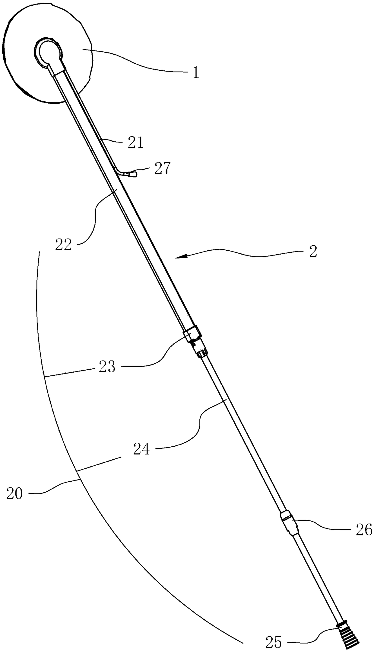
[0036] Embodiment 1, a suction cup piping device, such as figure 1 As shown, it includes a suction cup 1 and an outlet pipe 2 whose one end is integrally connected to the suction cup 1 . In the process of negative pressure cleaning, the suction cup 1 is connected to the biological semipermeable membrane sealing sponge and the entire wound surface and cavity, and at the same time, the end of the outlet pipe 2 away from the suction cup 1 is connected to the negative pressure source, and the suction is continued, so that the entire wound surface is fully closed The state of negative pressure drainage.

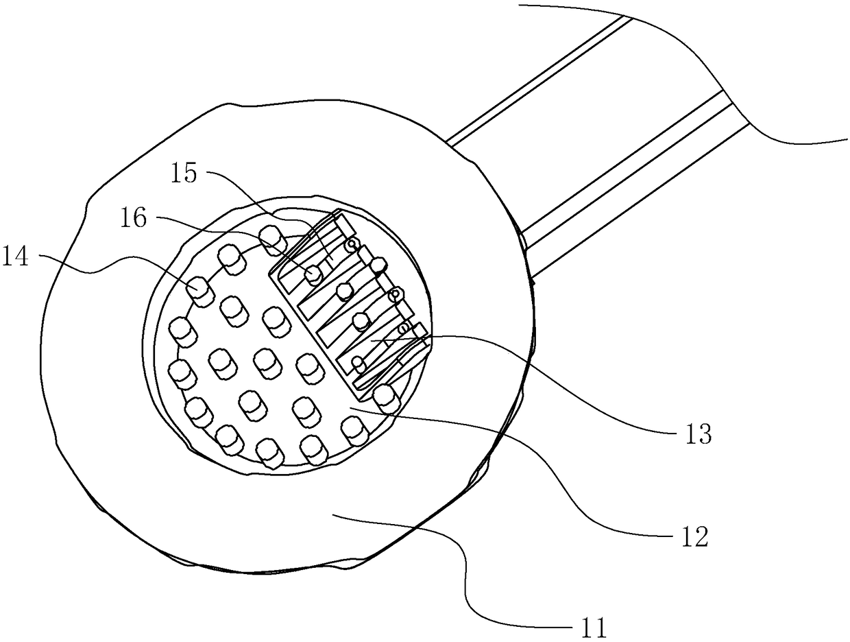
[0037] like figure 2 As shown, the suction cup 1 includes a ring-shaped fitting portion 11 disposed on the radially outer side and a concave portion 12 arranged on the radially inner side; the fitting portion 11 forms an annular closed space to ensure the fitting of the suction cup 1 . The inner concave portion 12 is recessed inward to form a vacuum cavity in the annular closed...

Embodiment 2

[0049] Embodiment 2: The difference between Embodiment 2 and Embodiment 1 lies in the structure of the inner lead-in end 13 of the concave portion 12 and the rib 14 . The lead-in end 13 extends into the cavity of the inner concave portion 12 in a flat tubular shape. The lead-in end 13 is provided with dividing bars 15 at equal intervals along the width direction. 13 is divided into multiple entrances. The protruding ribs 14 are elongated, and the elongated protruding ribs 14 are arranged in the inner concave portion 12 in a dotted line.

Embodiment 3

[0050] Embodiment 3: The difference between Embodiment 3 and Embodiment 1 lies in the structure of the inner lead-in end 13 of the concave portion 12 and the rib 14 . The lead-in end 13 extends into the cavity of the inner concave portion 12 in a flat tubular shape. The lead-in end 13 is provided with dividing bars 15 at equal intervals along the width direction. 13 is divided into multiple entrances. The protruding ribs 14 include a cylindrical central protruding rib 14 arranged in the middle and a waist-shaped columnar outer protruding rib 142 arranged on the radially outer side of the central protruding rib 141 . The number of the central protruding ribs 141 is four. Distributed at equal intervals along the circumferential direction, the outer convex ribs 142 are wrapped in three and a half layers on the outside of the middle convex ribs 141, and are distributed at equal intervals along the circumferential direction.


PUM


Abstract

The invention discloses a sucker line device and relates to the technical field of medical instruments. The sucker line device is technically characterized by comprising a sucker and a guide-out lineconnected to the sucker; the guide-out line includes a flat tube connected at one end to the sucker; an upper flat wall in plane form, a lower flat wall parallel to the upper flat wall and a connection wall to connect the upper and lower flat walls are arranged in the flat tube; ribs are arranged between the upper flat wall and the lower flat wall along the length direction; the ribs on the lowerflat wall and the ribs on the upper flat wall are staggered. The sucker line device has the advantages that a patient feels more comfortable after lying down and ventilation is stabilized.

Description

technical field [0001] The invention relates to the technical field of medical devices, and more particularly, to a suction cup pipeline device. Background technique [0002] The negative pressure drainage device refers to connecting the biological semipermeable membrane to seal the sponge and the entire wound surface and cavity with a suction cup, and at the same time connecting the drainage tube to the negative pressure source for continuous suction, so that the entire wound surface is in a state of fully closed negative pressure drainage, which can promote the wound surface. , The exudate and necrotic tissue in the cavity are excreted in time to keep the wound clean, at the same time accelerate the blood circulation of the wound, and promote the growth of new blood vessels and granulation tissue. The suction cup piping device is an accessory in the negative pressure closed drainage device. It mainly includes suction cups and lead-out pipelines. [0003] At present, the ...

Claims


Application Information

Patent Timeline
Patent Type & Authority Applications(China)
IPC IPC(8): A61M1/00
CPCA61M1/0023A61M1/84
Inventor 廖景明
Owner SUNEETEK XIAMEN MEDICAL EQUIP CO LTD
Why Eureka
Try Eureka