Cutter head structure of detachable electric shaver

A separate, shaver technology, applied in metal processing and other directions, can solve problems such as damage, inconvenient cleaning, and inability to replace, and achieve the effects of easy manufacturing, economical cost savings, and reasonable and practical structure

Inactive Publication Date: 2010-03-31
叶常明
View PDF2 Cites 34 Cited by
  • Summary
  • Abstract
  • Description
  • Claims
  • Application Information

AI Technical Summary

Problems solved by technology

[0004] 1. The traditional electric shaver is inconvenient to clean because the cutter head cannot be separated from the fuselage. When cleaning, water easily enters the fuselage and causes circuit damage.
[0005] 2. The rotation range of the knife net is limited by itself, so it is difficult to stick to some parts of the face well
[0006] 3. In addition, it is inconvenient or impossible to replace key vulnerable parts such as blades after they are broken
The transmission rim of the transmission unit is suspended for rotation about an axis of rotation which is oriented at an angle to each other and diverges from each other in the direction from the transmission rim to the connection end, the defect being that the shaft of the transmission unit is directly Fix the upper transmission gear, and the transmission gear meshes with the central gear. Since the transmission unit is connected with the cutting part, the angle needs to be adjusted under the pressure of the human face, resulting in unsatisfactory meshing between the transmission gear and the central gear. This transmission mechanism is unreasonable.

Method used


Image

  • Cutter head structure of detachable electric shaver
  • Cutter head structure of detachable electric shaver
  • Cutter head structure of detachable electric shaver

Examples


Embodiment Construction

[0037] The present invention will be further described in detail below in conjunction with the accompanying drawings and embodiments.

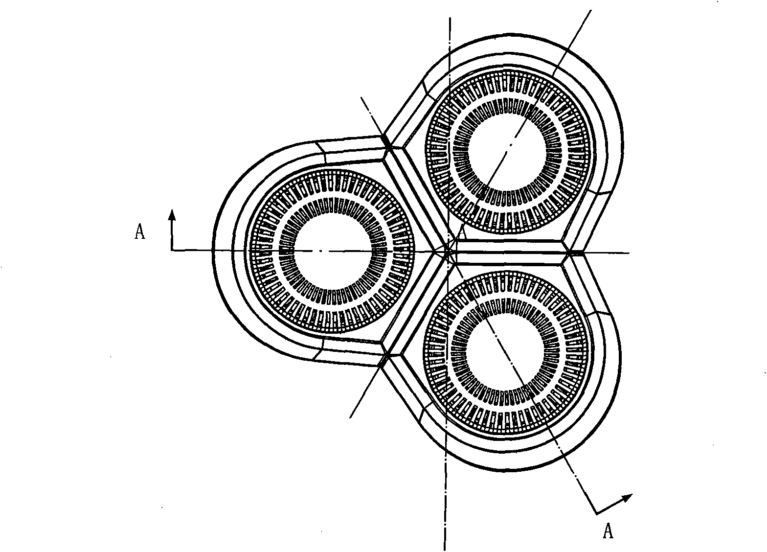
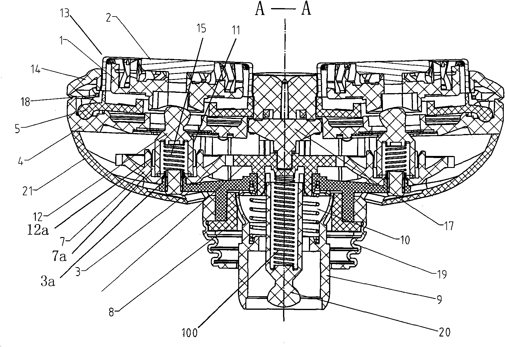
[0038] Such as Figure 1-16 As shown, a cutter head structure of a separate electric shaver includes a plurality of rotatable blades 1, a knife net 2, a main bracket 3, a rotating bracket 4, a pressing frame 5, a central rotating large gear 6, a transmission Main components such as pinion 7.

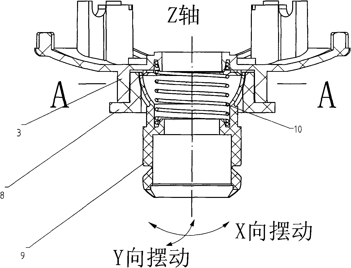
[0039] See Figure 2-5 , the main bracket 3 is set on the lower cover 8 of the main bracket and connected with buttons, and a spherical installation cavity is formed inside the lower cover 8 of the main bracket. , so that the main bracket lower cover 8 is connected with the cutter head connecting seat 9, and an elastic element 10 such as a spring is supported between the fixing groove of the main bracket 3 and the fixing groove of the cutter head connecting seat 9, thereby connecting the cutter head 9 has a downward pressure to allow the cutter head c...


PUM


Abstract

The invention relates to a cutter head structure of a detachable electric shaver, comprising a plurality of cutter blade assemblies capable of rotatably cutting, and the cutter blade assemblies are injoggled connection with a central transmission gearwheel on a main support by respective transmission unit. The cutter head structure is characterized in that the main support is sleeved on the lowercover of the main support, whereas the lower cover of the main support is connected with a cutter blade connecting seat by spherical coordination; and an elastic element is supported between the mainsupport and the cutter blade connecting seat. The cutter head structure has big rotational degree of freedom, simple and practical structure and easy manufacture.

Description

technical field [0001] The invention relates to a cutter head structure of a separate electric shaver. Background technique [0002] The traditional electric shavers on the market have single-head, double-head or three-head, and most of the cutter heads are connected with the body. There is a certain angle that can be rotated freely, so that the shaver net can fit the complex facial surface of the human body. [0003] But there are three problems with traditional razors: [0004] 1. The traditional electric shaver is inconvenient to clean because the cutter head cannot be separated from the fuselage. When cleaning, water easily enters the fuselage and causes circuit damage. [0005] 2. The rotation range of the knife net is limited by itself, so it is difficult to stick to some parts of the face well. [0006] 3. In addition, it is inconvenient or impossible to replace key vulnerable parts such as blades after they are broken. [0007] In addition, the Chinese patent No....

Claims


Application Information

Patent Timeline
Patent Type & Authority Applications(China)
IPC IPC(8): B26B19/14B26B19/38
CPCB26B19/14B26B19/145B26B19/146
Inventor 谢质彬叶常明
Owner 叶常明
Why Eureka
Try Eureka