Supercharge Your Innovation With Domain-Expert AI Agents!

Method and device for monitoring the function of a rotational speed regulator

A technology of speed regulator and regulator, which is applied in the direction of governor, engine control, machine/engine, etc., and can solve troubles and other problems

Active Publication Date: 2012-02-01
ROBERT BOSCH GMBH
View PDF0 Cites 0 Cited by
  • Summary
  • Abstract
  • Description
  • Claims
  • Application Information

AI Technical Summary

Problems solved by technology

this is very troublesome

Method used


Image

  • Method and device for monitoring the function of a rotational speed regulator
  • Method and device for monitoring the function of a rotational speed regulator
  • Method and device for monitoring the function of a rotational speed regulator

Examples


Embodiment Construction

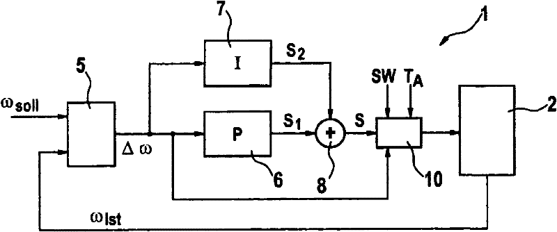
[0019] figure 1 An engine system 1 with an internal combustion engine 2 and a rotational speed regulator is schematically shown. The rotational speed regulator is designed as a PI controller, for example, and provides a control variable S in the form of, for example, a control torque or a fuel quantity to be injected as a function of the rotational speed difference Δω. The rotational speed regulator comprises a differential element 5 for calculating the setpoint rotational speed ω provided externally (eg according to the driver's desired torque on the vehicle) Soll and the actual rotational speed ω detected in the internal combustion engine 2 Ist speed difference between them. The rotational speed difference Δω is supplied to the proportional element 6 (P controller part) and the integrating element 7 (I controller part) of the controller. The proportional element 6 and the integral element 7 respectively provide part of the adjustment parameter S 1 or S 2 , the partial a...


PUM


Abstract

The invention relates to a method and an apparatus for monitoring a function of a rotational speed regulating means of an internal combustion engine (2). Here, an exceeding of the rotational speed is detected if an actual rotational speed (?Ist) of the internal combustion engine exceeds a setpoint rotational speed (?Soll) by more than a predefined threshold value (SW). If an exceeding of the rotational speed is detected, a manipulated variable (S) of the rotational speed regulating means is limited to a maximum manipulated variable (Mmax) which drops over time.

Description

technical field [0001] The invention relates to a method and a device for monitoring the function of a speed regulator, in particular in the thrust monitoring function of a diesel engine control system. Background technique [0002] In diesel engine control systems, thrust monitoring can be activated as a fault handling function when the actual speed is higher than the setpoint speed by more than a predetermined threshold value. When thrust monitoring is activated, it is necessary for the rotational speed regulator to set its corresponding control variable to zero so quickly that the injection is cut off after a predetermined duration, for example one second, including all other delayed functions, This means setting the trigger duration of the injector to zero. [0003] The speed regulator provided in the engine control system works according to the field of use, that is to say depending on the manufacturer of the vehicle or depending on the vehicle with different parameter...

Claims


Application Information

Patent Timeline
Patent Type & Authority Patents(China)
IPC IPC(8): F02D31/00
CPCF02D31/009
Inventor G·科特纳克S·麦罗诺夫K·施瓦泽
Owner ROBERT BOSCH GMBH
Features
  • R&D
  • Intellectual Property
  • Life Sciences
  • Materials
  • Tech Scout
  • Unparalleled Data Quality
  • Higher Quality Content
  • 60% Fewer Hallucinations
Learn More