
Test method for dynamic working conditions of vehicle electric drive system

A technology of electric drive system and test method, which is applied in the direction of vehicle testing, machine/structural component testing, measuring devices, etc. It can solve the problem of ignoring the working state of the battery pack, the source of energy feedback, driving resistance energy consumption, and testing the characteristics of the whole vehicle Lack of other issues

Active Publication Date: 2011-12-28
TSINGHUA UNIV
View PDF0 Cites 0 Cited by
  • Summary
  • Abstract
  • Description
  • Claims
  • Application Information

AI Technical Summary

Problems solved by technology

[0003] Most of the domestic test benches use dynamometers as loading equipment to test the on-board motor and its control. The embodiment of resistance energy consumption
Such a test bench is lacking in testing the characteristics of the whole vehicle

Method used


Image

  • Test method for dynamic working conditions of vehicle electric drive system
  • Test method for dynamic working conditions of vehicle electric drive system

Examples


Embodiment Construction

[0013] The present invention will be described in detail below in conjunction with the embodiments.

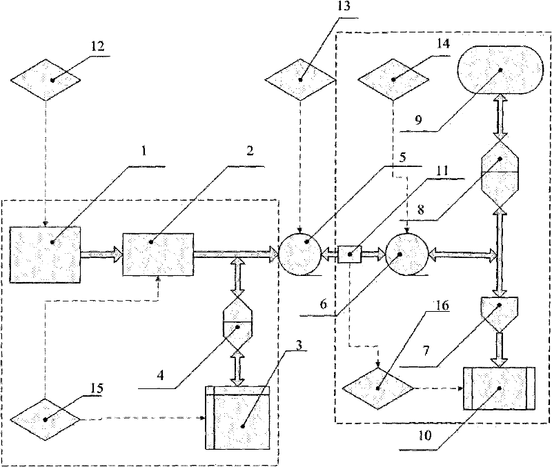
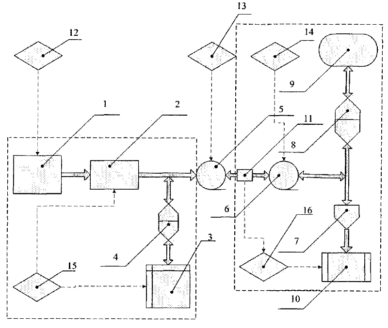
[0014] refer to figure 1 , when the vehicle is in the driving state, the fuel cell simulator 1 and the battery pack 3 jointly provide electric energy to the on-board motor 5 under the coordinated control of the power regulation controller 15, and the on-board motor 5 converts the electric energy under the control of the on-board motor controller 13 In order to transfer the mechanical energy to the load motor 6, the load motor controller 14 obtains the power demand by calculating the current vehicle speed and acceleration, etc., thereby controlling the load motor 6 to convert the mechanical energy into electric energy, while the load simulation controller 16 calculates the driving resistance (including rolling resistance, Air resistance, etc.) account for the proportion of the total power, and control the power consumed by the resistance box 10. At this time, the electric energ...


PUM


Abstract

The invention relates to a dynamic working condition test method of a vehicle electric drive system, which belongs to the technical field of electric vehicles. The output shaft of the on-board motor is connected to the output shaft of the load motor on the same axis. When driving, the power of the drive system is transmitted from the on-board motor to the load motor and converted into electrical energy stored in the super capacitor or consumed in the resistance box; when braking, the energy is transmitted by the super capacitor. The consumption by the resistance box is fed back to the battery pack through the load motor and the on-board motor; the operation of the load motor is controlled to simulate the actual load torque; the load simulation controller calculates the energy consumed by the driving resistance according to the current cycle speed, vehicle parameters and road conditions The power and the power converted into vehicle kinetic energy control the resistance of the resistance box, that is, the energy consumed by the control resistance box is equal to the energy consumed by the driving resistance. The invention can be used alone for the research of the drive control strategy and the brake control strategy, and can also be used for the research of the whole vehicle control strategy, and is more convenient.

Description

technical field [0001] The invention relates to a method for simulating the running conditions of an electric vehicle on a stand, that is, a scheme for simulating the running conditions of the vehicle-mounted motor by loading the vehicle-mounted motor, and belongs to the technical field of electric vehicles. Background technique [0002] At present, the country puts the vigorous development of electric vehicles on the agenda. In the entire electric vehicle powertrain, the basic performance and control effect of the motor are the direct factors that affect the performance index of the vehicle. Therefore, a system that can reflect the characteristics of the motor under automotive conditions is of great significance. Taking the prototype car as the test object, although the corresponding motor results can be obtained very well, but it is not the first choice for the initial stage of R&D because of its heavy workload, long cycle, high cost, and limitations of the test site. A ...

Claims


Application Information

Patent Timeline
Patent Type & Authority Patents(China)
IPC IPC(8): G01M17/007
Inventor 张俊智柳贵东何承坤
Owner TSINGHUA UNIV
Learn More