
Method for preventing broken pieces of band tail from blocking shearing when shearing band tail of cold rolled strip steel production unit

A technology of cold-rolling strip steel and chips, which is applied in the direction of rolling mill control devices, metal rolling, metal rolling, etc., and can solve problems affecting the production continuity of the unit and reducing the production efficiency of the unit

Active Publication Date: 2012-05-30
WISDRI WUHAN AUTOMATION
View PDF0 Cites 0 Cited by
  • Summary
  • Abstract
  • Description
  • Claims
  • Application Information

AI Technical Summary

Problems solved by technology

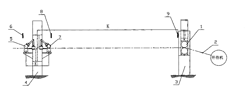
The length of the unqualified part of the strip tail is produced in the last processing procedure of the strip steel, which is an uncertain variable. If it is cut with a fixed length, the length of the last fragment will be less than figure 1 The length of medium K1, at this time the last piece of debris will be stuck between the inlet and outlet pinch rollers of the scissors and cannot be moved, and finally can only be processed manually, which greatly affects the continuity of the production of the unit and reduces the production efficiency of the unit

Method used

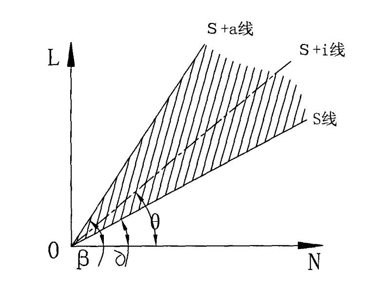
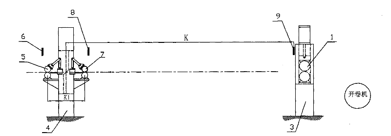

Image

  • Method for preventing broken pieces of band tail from blocking shearing when shearing band tail of cold rolled strip steel production unit
  • Method for preventing broken pieces of band tail from blocking shearing when shearing band tail of cold rolled strip steel production unit
  • Method for preventing broken pieces of band tail from blocking shearing when shearing band tail of cold rolled strip steel production unit

Examples


Embodiment 1

[0058] first as image 3 As shown in the figure, the tape tail escapes from the coiler after the tailing of the unit is completed, and when the tape tail passes the entrance and turns to the photoelectric cell 9 at the exit of the pinch roller, the passage of the tape tail is calculated by the rotary encoder installed on the 7-axis of the entrance shear and entrance pinch roller The entrance turns to the distance of the photocell 9 at the exit of the pinch roller, and the distance between the entrance and the photocell 9 at the exit of the pinch roller and the entrance shear is known as K, so that the remaining tail length L1=1.5m that needs to be cut can be calculated; At this time, the total length L1 of the remaining tape tail that needs to be cut is directly below the entrance shear, and the first knife cut is performed to complete the separation of the qualified and unqualified parts of the tape tail; the unqualified part is the remaining waste to be cut. At this time, Th...

Embodiment 2

[0062] first as image 3 As shown in the figure, the tape tail escapes from the coiler after the tailing of the unit is completed, and when the tape tail passes the entrance and turns to the photoelectric cell 9 at the exit of the pinch roller, the passage of the tape tail is calculated by the rotary encoder installed on the 7-axis of the entrance shear and entrance pinch roller The entrance turns to the distance of the photocell 9 at the exit of the pinch roller, and the distance between the entrance and the photocell 9 at the exit of the pinch roller and the entrance shear is known as K, so that the remaining tail length L1=5.3m that needs to be cut can be calculated; At this time, the total length L1 of the remaining tape tail that needs to be cut is directly below the entrance shear, and the first knife cut is performed to complete the separation of the qualified and unqualified parts of the tape tail; the unqualified part is the remaining waste to be cut. At this time, Th...

Embodiment 3

[0070] first as image 3 As shown in the figure, the tape tail escapes from the coiler after the tailing of the unit is completed, and when the tape tail passes the entrance and turns to the photoelectric cell 9 at the exit of the pinch roller, the passage of the tape tail is calculated by the rotary encoder installed on the 7-axis of the entrance shear and entrance pinch roller The entrance turns to the distance of the photocell 9 at the exit of the pinch roller, and the distance between the entrance and the photocell 9 at the exit of the pinch roller and the entrance shear is known as K, so the total length L1 of the remaining tail that needs to be cut can be calculated = 3.99m; At this time, the total length L1 of the remaining tape tail that needs to be cut is directly below the entrance shear, and the first knife cut is performed to complete the separation of the qualified and unqualified parts of the tape tail; the unqualified part is the remaining waste to be cut. At thi...


PUM


Abstract

The invention belongs to the field of automatic control of metallurgical cold rolling, in particular to a method for preventing broken pieces of a band tail from blocking shearing when shearing the band tail of a cold rolled continuous strip steel production unit. The method comprises the steps of calculating the distance of the band tail from an inlet to a photoelectric tube at an outlet of a pinch roller and further calculating the total length L1 of the residual band tail which nees to be sheared (when carrying out first-cut shearing, L1=L); the ideal length l of each broken piece is in a range, the number N of shearing cuts is constantly adjusted according to the total length L of the residual waste material to be sheared, thereby always leading the value of L / N to fall in the range of l and further ensuring that each broken piece of the sheared band tail, including the last piece can smoothly pass through a pair of shears at the inlet and be conveyed into a waste material device (which can prevent the broken pieces of the band tail from blocking shearing). The method can prevent the broken pieces of the band tail from blocking shearing when shearing the band tail of the cold rolled strip steel production unit.

Description

technical field [0001] The invention belongs to the field of automatic control of metallurgical cold rolling, and in particular relates to a method for preventing strip tail fragments from being stuck and sheared when the strip tail of a cold rolling continuous strip steel production unit is cut. Background technique [0002] The cold-rolled strip steel production unit is a continuous production unit that produces continuous ordinary carbon steel, non-oriented silicon steel, and oriented silicon steel. The steel strip is opened, processed, and recoiled on the unit in a physical manner as a steel coil. In this working mode, there must be a gap between the tail of the strip being produced and the head of the strip to be produced in order to ensure the continuous operation of the unit. The process of welding. In order to ensure the welding quality, it is necessary to carry out shearing treatment on the tail of the strip steel being produced, so as to cut the unqualified parts ...

Claims


Application Information

Patent Timeline
Patent Type & Authority Patents(China)
IPC IPC(8): B21B15/00B21B37/00
Inventor 徐敏叶刚桥
Owner WISDRI WUHAN AUTOMATION
Learn More