Energy conversion device and automobile with same

A technology for energy conversion devices and automobiles, which can be applied to control devices, auxiliary drive devices, vehicle components, etc., and can solve problems such as energy waste.

Inactive Publication Date: 2010-06-16
BYD CO LTD
View PDF0 Cites 2 Cited by
  • Summary
  • Abstract
  • Description
  • Claims
  • Application Information

AI Technical Summary

Problems solved by technology

Most of the existing fuel vehicles have not taken corresponding measures for the utilization of these energies, resulting in a waste of these energies; currently, due to the constraints of environmental factors, hybrid vehicles and electric vehicles are developing vigorously, and some hybrid and elec

Method used


Image

  • Energy conversion device and automobile with same
  • Energy conversion device and automobile with same
  • Energy conversion device and automobile with same

Examples


Embodiment 1

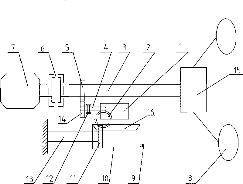
[0013] Such as figure 1 As shown, an energy conversion device includes an energy transfer mechanism, an energy storage mechanism and a control mechanism, one end of the energy transfer mechanism is connected to the energy storage mechanism, and the control mechanism controls the energy transfer mechanism to input external mechanical energy into the energy storage mechanism and output the energy in the energy storage mechanism to the working parts.

[0014] The energy transmission mechanism is a group of transmission components 1, which can be a gear transmission group, a belt transmission group, a chain transmission group, a cycloid transmission group, etc., preferably a gear transmission group, and the gear transmission group 1 includes a Output gear 2. The gear transmission set 1 contains a gear locking mechanism, and the energy transfer device can lock or unlock the gear transmission set 1 through the gear locking mechanism.

[0015] The energy storage mechanism includes ...

Embodiment 2

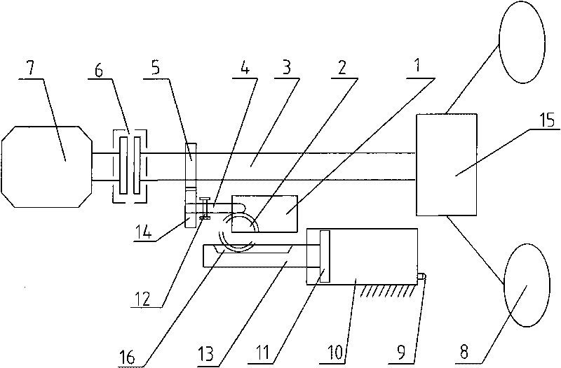
[0019] Such as figure 2 As shown, an energy conversion device includes an energy transfer mechanism, an energy storage mechanism and a control mechanism, one end of the energy transfer mechanism is connected to the energy storage mechanism, and the control mechanism controls the energy transfer mechanism to input external mechanical energy into the energy storage mechanism and output the energy in the energy storage mechanism to the working parts.

[0020] The energy transmission mechanism is a group of transmission components 1, which can be a gear transmission group, a belt transmission group, a chain transmission group, a cycloid transmission group, etc., preferably a gear transmission group, and the gear transmission group 1 includes a Output gear 2. The gear transmission set 1 contains a gear locking mechanism, and the energy transfer device can lock or unlock the gear transmission set 1 through the gear locking mechanism.

[0021] The energy storage mechanism includes...


PUM


Abstract

The invention provides an energy conversion device comprising an energy transferring mechanism, an energy storing mechanism and a controlling mechanism. One end of the energy transferring mechanism is connected with the energy storing mechanism. The controlling mechanism is used for controlling the energy transferring mechanism to input the external mechanical energy into the energy storing mechanism and output the energy in the energy storing mechanism to the working parts. The invention also provides an automobile comprising a drive shaft, a speed reducing mechanism, wheels and the energy transferring mechanism. The drive shaft is connected with the wheels through the speed reducing mechanism. Due to the adoption of the technical scheme, the invention can collects the energy generated when the automobile is in the neutral position or in the speed reducing state so as to assisting the automobile with power for starting, accelerating or climbing the slope.

Description

technical field [0001] The invention belongs to the technical field of energy conversion, in particular to an energy recovery and release device for automobiles. Background technique [0002] With the continuous development of technology and the continuous improvement of people's living standards, automobiles have already become an indispensable means of transportation for many people's daily travel. During the braking process, the inertia of deceleration, the inertia of mechanical movement and the energy at idle speed, etc. Most of the existing fuel vehicles have not taken corresponding measures for the utilization of these energies, resulting in a waste of these energies; currently, due to the constraints of environmental factors, hybrid vehicles and electric vehicles are developing vigorously, and some hybrid and electric vehicles are in use. The energy feedback mode is adopted in the design process, that is, when the vehicle is decelerating, idling or braking, the kinet...

Claims


Application Information

Patent Timeline
IPC IPC(8): B60K25/10
Inventor 付多智
Owner BYD CO LTD
Why Eureka
Try Eureka