Hydraulic grooving saw

A groove sawing machine and hydraulic technology, which is applied in the direction of earth mover/shovel, construction, etc., can solve the problems of complex construction technology, high equipment cost, and large power consumption.

Inactive Publication Date: 2010-06-16
南通阿斯通电器制造有限公司
View PDF0 Cites 24 Cited by
  • Summary
  • Abstract
  • Description
  • Claims
  • Application Information

AI Technical Summary

Problems solved by technology

[0002] At present, most of the equipment used in the construction of underground diaphragm walls has the disadvantages of high power consumption, low efficiency, complicated construction technology, and high cost of construction equipment.

Method used


Image

  • Hydraulic grooving saw
  • Hydraulic grooving saw

Examples


Embodiment Construction

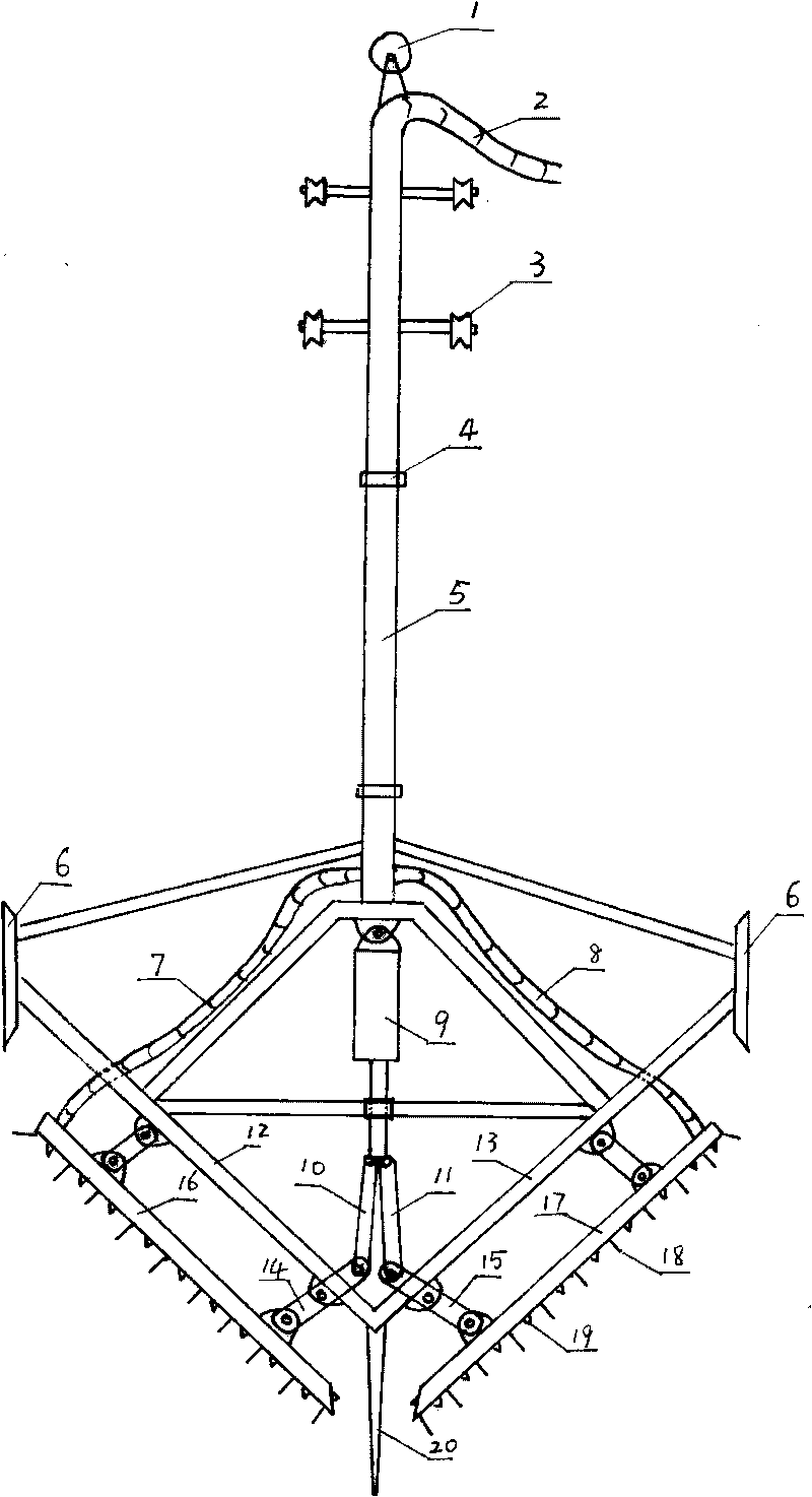
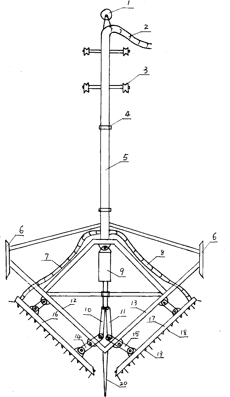
[0008] The accompanying drawing is a specific embodiment of the present invention, which includes an upper water inlet hose 2, a water inlet pipe 5, and a threaded joint 4 at both ends of the water inlet pipe for connecting the two water inlet pipes, a left water inlet hose 7, and a right water inlet hose. The rubber hose 8 and the water nozzle 19, the lower end of the hydraulic shaft of the hydraulic cylinder 9 are pinned to the left connecting rod 10 and the right connecting rod 11, the lower end of the left connecting rod 10 is pinned to the upper end of the left rocking wall 14, the lower end of the left rocking arm is connected to the The left saw bar 16 is pinned, the middle pin is connected to the left saw frame 12, the lower end of the right connecting rod 11 is pinned to the upper end of the right rocker arm 15, the lower end of the right rocker is pinned to the right saw bar 17, and the middle pin is connected to the On the right saw frame 13, the limit pin 20 is posi...


PUM


Abstract

The invention discloses a hydraulic grooving saw, comprising an upper water feeding hose, two water feeding pipes, two screw joints, left and right water feeding hoses and water spray nozzles, wherein the two screw joints for connecting two water feeding pipes are arranged at two ends of one water feeding pipe; the hydraulic grooving saw is characterized in that the lower end of a hydraulic shaft of a hydraulic oil cylinder is connected with a left connecting rod and a right connecting rod by pins, the lower ends of the left connecting rod and the right connecting rod are respectively connected with a left rocking arm and a right rocking arm by pins, the lower ends of the left rocking arm and the right rocking arm are respectively connected with a left sawing rod and a right sawing rod by pins, the middle parts of the left rocking arm and the right rocking arm are respectively connected with a left sawing frame and a right sawing frame by pins, a limit needle is located at the lower part of the grooving saw, a left guide plate and a right guide plate are respectively located at a left side and a right side of the grooving saw, and four trail wheels are located at the upper ends of the water feeding pipes.

Description

1. Technical field [0001] The invention relates to a groove sawing machine, in particular to a hydraulic groove sawing machine for an underground continuous wall 2. Background technology [0002] At present, most of the equipment used in the construction of underground diaphragm walls has the disadvantages of high power consumption, low efficiency, complicated construction technology, and high cost of construction equipment. 3. Contents of the invention [0003] The invention provides a hydraulic groove sawing machine with low power consumption, high efficiency, simple construction method and low cost for construction equipment. [0004] The present invention is achieved through the following technical solutions: [0005] A hydraulic trough sawing machine comprises an upper water inlet rubber hose, a water inlet pipe, threaded joints at both ends of the water inlet pipe for connecting the two water inlet pipes, left and right water inlet rubber hoses and water spray nozzl...

Claims


Application Information

Patent Timeline
Patent Type & Authority Applications(China)
IPC IPC(8): E02F5/02
Inventor 张永忠
Owner 南通阿斯通电器制造有限公司
Why Eureka
Try Eureka