Compression joint method of compression joint barrel, compression joint barrel and compression joint device

A crimping terminal and mounting structure technology, applied in the direction of two-part connection device, coupling device, connection, etc., can solve problems such as difficult to achieve bending processing state, achieve a good and stable crimping state, increase the number of processing steps, top wall side flat effect

Inactive Publication Date: 2010-06-23
YAZAKI CORP
View PDF1 Cites 9 Cited by
  • Summary
  • Abstract
  • Description
  • Claims
  • Application Information

AI Technical Summary

Problems solved by technology

[0010] However, whether or not a flat state can be obtained for the upper part of the two top walls 120 depends particularly on the dimension in the width direction, so when the dimensional deviation increases, it is difficult to achieve a good bending state.

Method used


Image

  • Compression joint method of compression joint barrel, compression joint barrel and compression joint device
  • Compression joint method of compression joint barrel, compression joint barrel and compression joint device
  • Compression joint method of compression joint barrel, compression joint barrel and compression joint device

Examples


Embodiment Construction

[0073] Hereinafter, the best mode for carrying out the present invention will be described in detail with reference to the drawings.

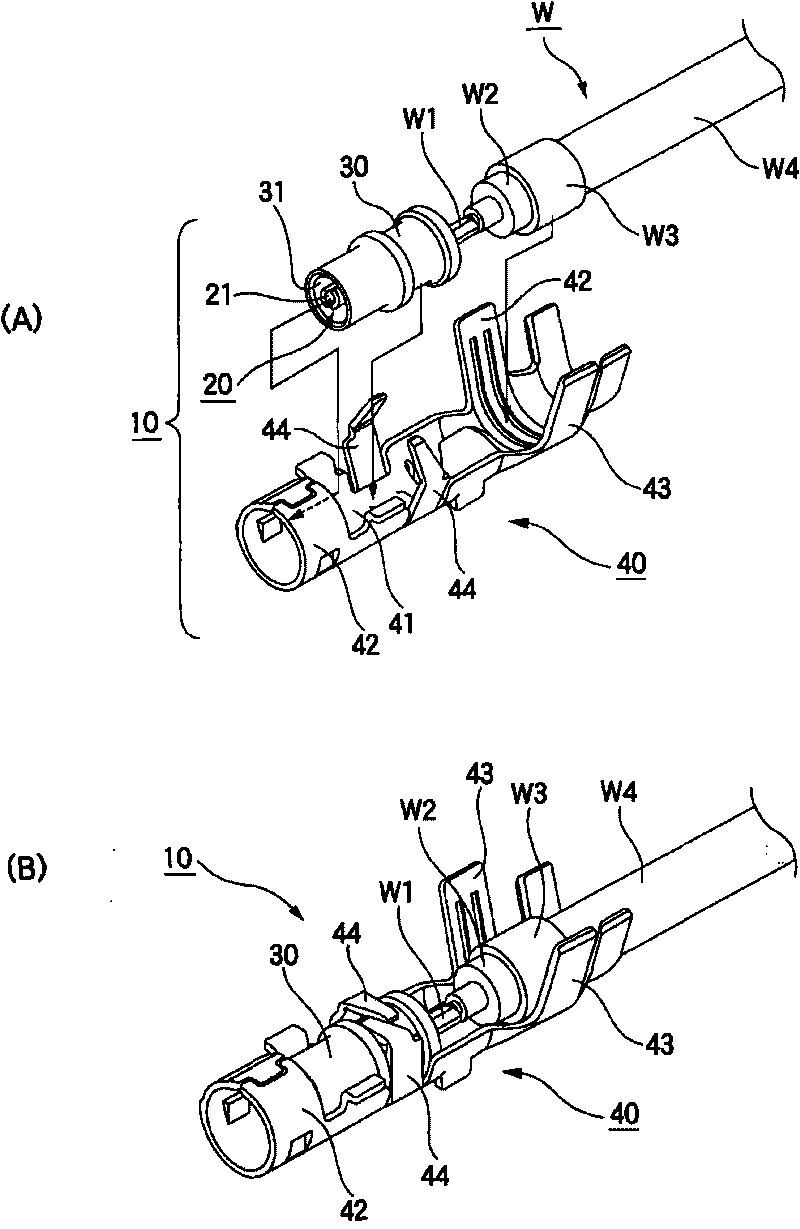
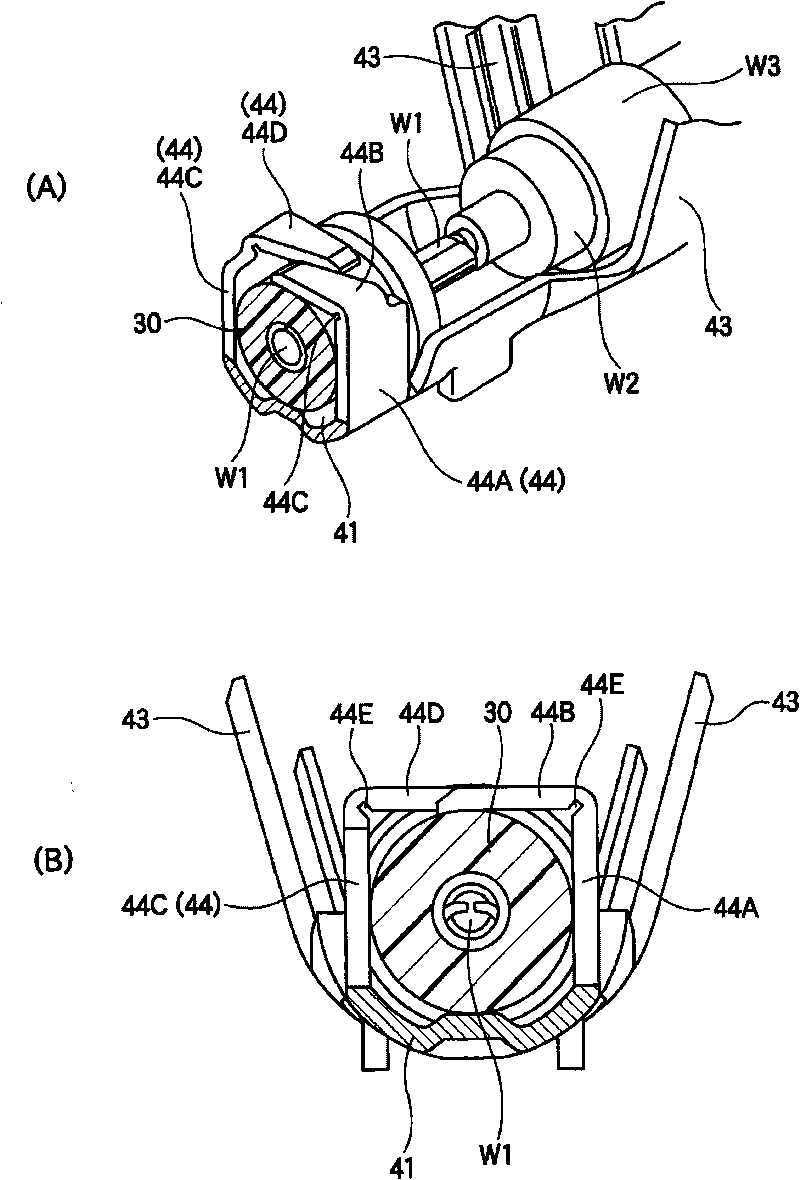
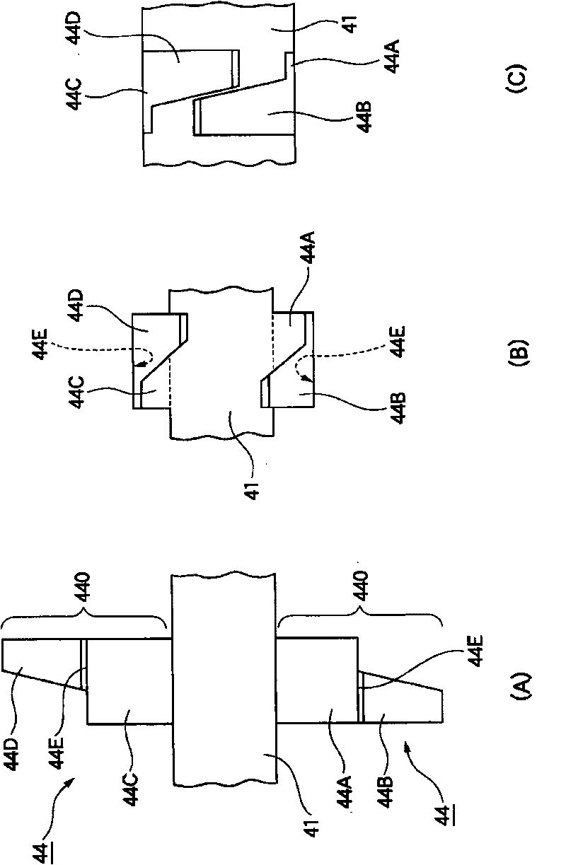
[0074] figure 1 (A) and (B) are respectively an exploded perspective view of the shielded wire connector 10 before using the crimping structure according to the embodiment of the present invention and a perspective view of main parts of the shielded wire connector 10 using the crimping structure. figure 2 (A) is a sectional perspective view of main parts of a connector with a shielded wire according to an embodiment of the present invention in a state of being attached to a shielded wire, figure 2 (B) is its cross-sectional front view. image 3 (A) to (C) are plan views illustrating states when the crimping barrel portion is processed by the crimping barrel crimping method of the present invention, respectively. Figure 4 It is an explanatory view showing a crimping device and the like used in the crimping method of the crimping barrel of ...


PUM


Abstract

The invention provides a compression joint method of a compression joint barrel without increasing the number of processing operations, wherein the top wall part after compression joint can realize flatness. In the compression joint method, the protuberance and the top wall part are compressed till contacted with an insulated part, and the top wall part is further compressed by compressing the protuberance; therefore, the top wall part is bended by using the part contacted with the insulated part of the top wall part as a pivot point.

Description

technical field [0001] The present invention relates to a crimping method, a crimping method, and a crimping method for a crimping cylinder suitable for crimping in a connector with a shielded wire (for example, an antenna plug connector) that is electrically connected to an end portion of a shielded wire (coaxial cable). Sockets and crimping devices for this. Background technique [0002] As is well known, a large number of various terminals have been developed and used in the prior art. For example, female terminals used in connectors for automobiles and the like are known, and the method described in Patent Document 1, for example, is known as a method for manufacturing the female terminals. [0003] That is, the female terminal as Figure 10 As shown, the metal processing plate is processed to obtain the raw material 100 of the female terminal. Next, if Figure 11 As shown, the raw material 100 is loaded on the base 200 and pressed from above by the pressing member 21...

Claims


Application Information

Patent Timeline
Patent Type & Authority Applications(China)
IPC IPC(8): H01R43/16H01R43/048H01R24/20H01R24/38H01R24/40H01R24/86
Inventor 森川大史
Owner YAZAKI CORP
Why Eureka
Try Eureka