Method for outputting synchronous time, device and system thereof

A technology for synchronizing time and time, applied in the field of communication transmission, can solve the problems such as the inability to realize low-cost time backup and the inability to provide high-precision synchronization time, and achieve the effect of low cost

Active Publication Date: 2010-07-21
HUAWEI TECH CO LTD
View PDF2 Cites 18 Cited by
  • Summary
  • Abstract
  • Description
  • Claims
  • Application Information

AI Technical Summary

Problems solved by technology

[0013] In view of this, the embodiment of the present invention provides a method, device and system for outputting synchronization time, which overcomes the technical problems in the prior art that cannot provide high-precision synchronization time, and cannot realize low-cost time backup

Method used


Image

  • Method for outputting synchronous time, device and system thereof
  • Method for outputting synchronous time, device and system thereof
  • Method for outputting synchronous time, device and system thereof

Examples


Embodiment 3

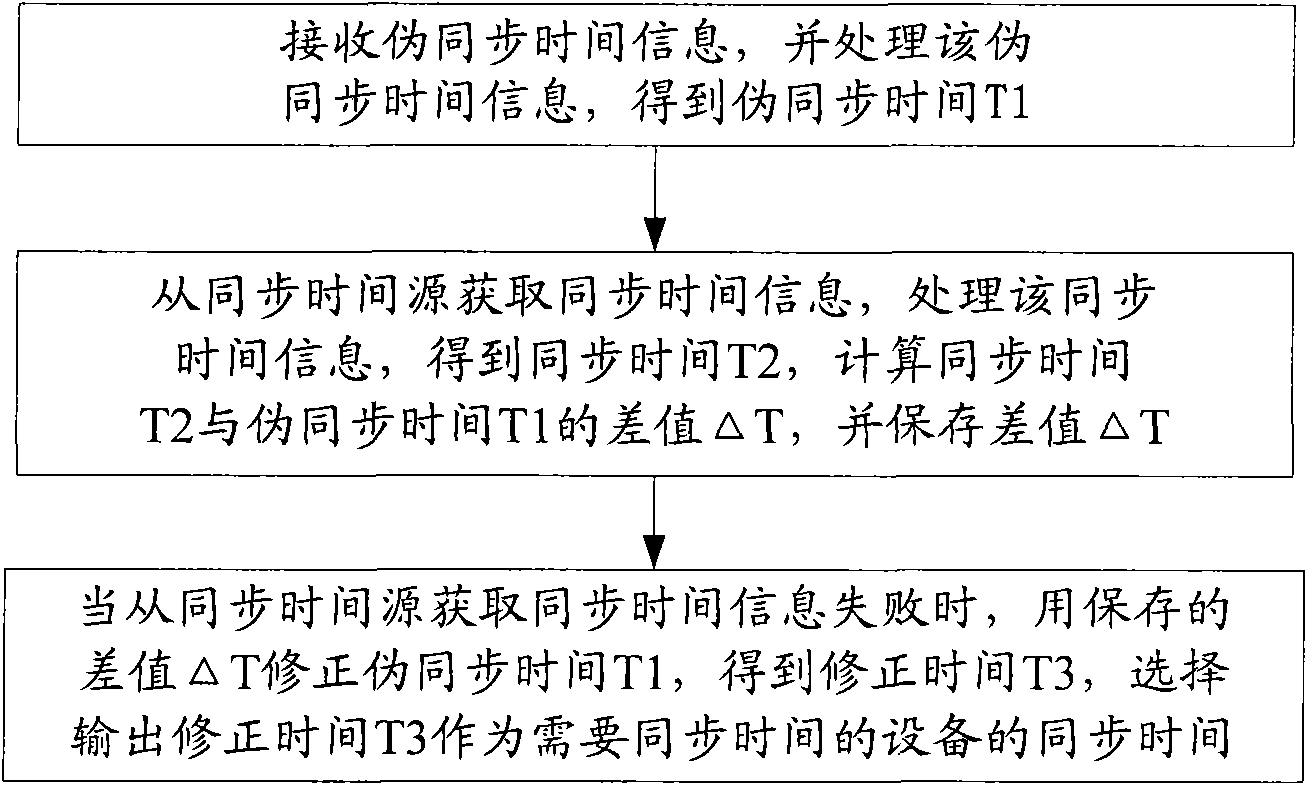
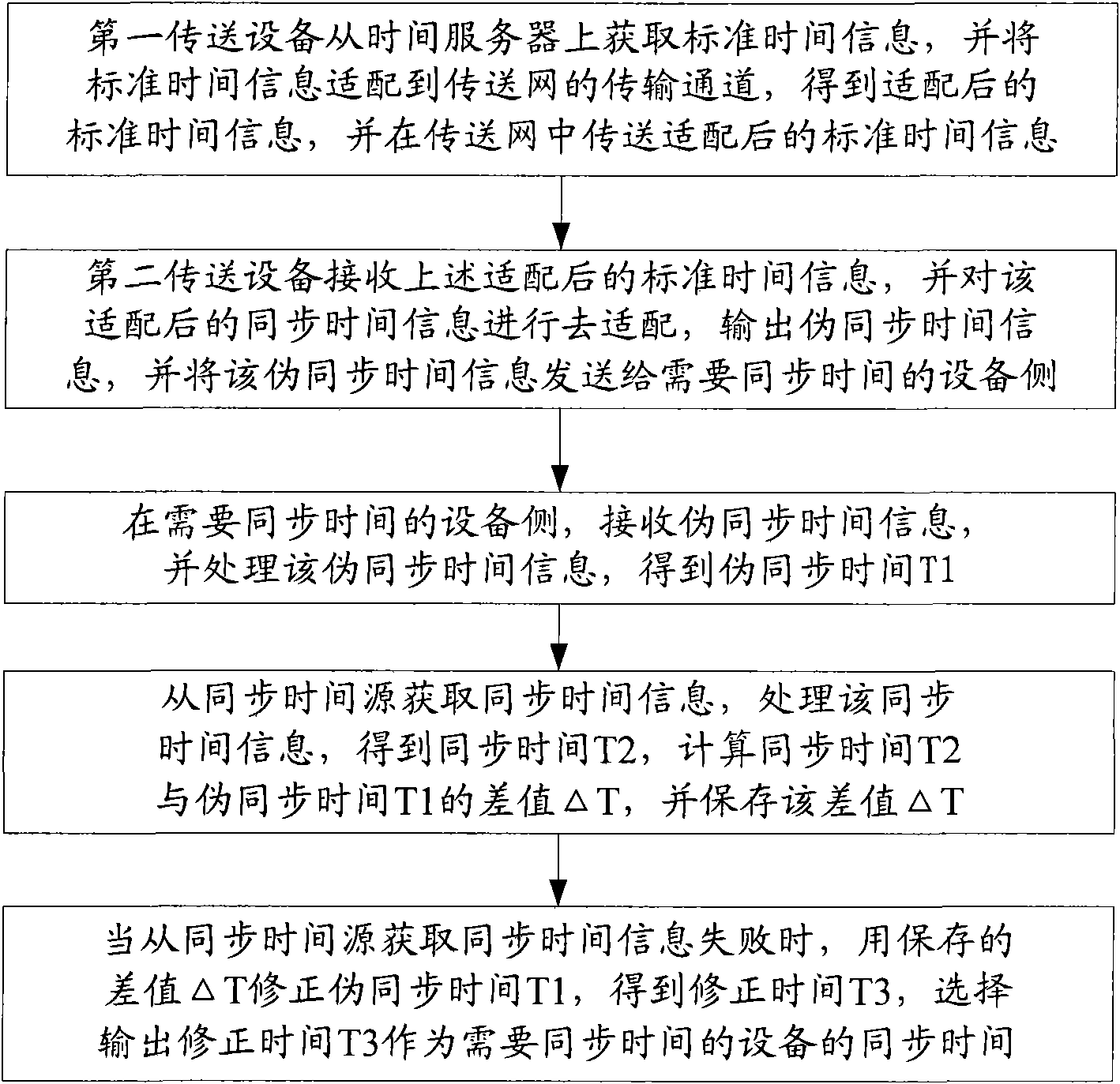
[0057] The flow chart of a method for output synchronization time based on the transmission network in Embodiment 3 is as follows: image 3 As shown, the method includes:

[0058] The first transmission device acquires standard time information from the time server, adapts the standard time information to the transmission channel of the transmission network, obtains the adapted standard time information, and transmits the adapted standard time in the above-mentioned transmission network information;

[0059] The second transmission device receives the adapted standard time information, de-adapts the adapted standard time information, outputs pseudo-synchronized time information, and sends the pseudo-synchronized time information to the device side that needs synchronized time;

[0060] On the side of the device that needs to synchronize time, process the above pseudo-synchronized time information, and output the synchronized time. On the side of the device that needs to sync...

Embodiment 4

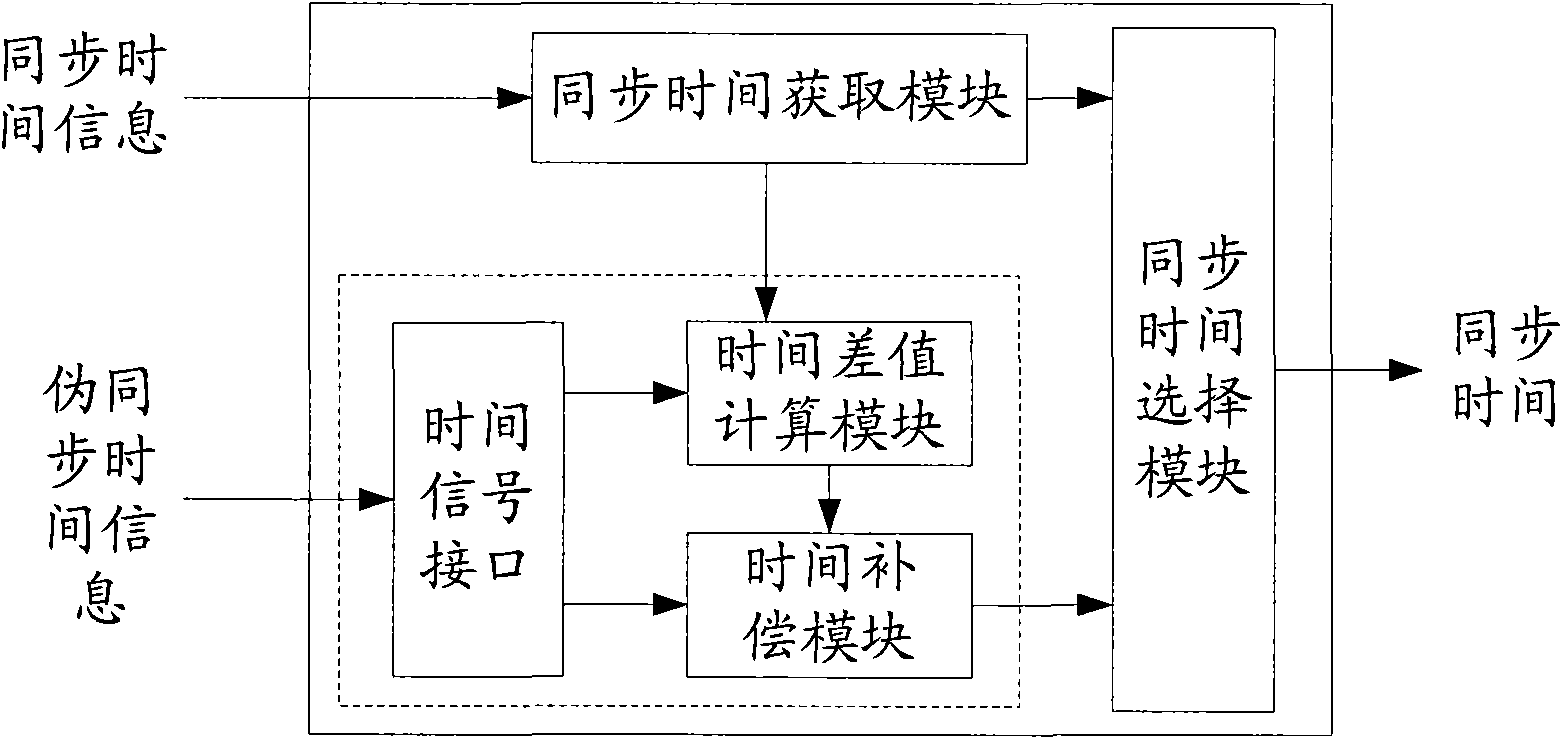
[0071] In Embodiment 4, a system structure diagram of a transmission network-based output synchronization time is as follows: Figure 4 As shown, the system includes:

[0072] The first transmission device, the second transmission device and the device for outputting the synchronized time, the first transmission device and the second transmission device are located in the same transmission network;

[0073] The first transmission device is used to obtain standard time information from the time server, adapt the standard time information to the transmission channel of the transmission network, obtain the adapted standard time information, and transmit the adapted standard time information in the transmission network Synchronized time information after configuration;

[0074] The second transmission device is configured to receive the adapted standard time information, de-adapt the adapted standard time information, and output pseudo-synchronized time information;

[0075] The...


PUM


Abstract

The embodiment of the invention relates to the field of communication transmission, and particularly discloses a method for acquiring synchronous time, a device and a system thereof. The method comprises the following steps: receiving pseusynchronous time information, processing the pseusynchronous time information and obtaining pseusynchronous time T1; acquiring synchronous time information from a synchronous time source, processing the synchronous time source, obtaining synchronous time T2, calculating a time difference value Delta T of the synchronous time T2 and the pseusynchronous time T1 and storing the difference value Delta T; and when failing to acquire synchronous time information from the synchronous time source, correcting the pseusynchronous time T1 with the stored time difference value Delta T, obtaining corrected time T3 and selecting, and outputting the corrected time T3 as synchronous time of equipment needing to synchronize time. The invention solves the problem that in the prior art, the transmission delays of the two-way transmission channel of the transmission network are different so as to cause low accuracy and the like of the synchronous time obtained by operating the network time protocol.

Description

technical field [0001] The invention relates to the field of communication transmission, in particular to a method, device and system for obtaining output synchronization time. Background technique [0002] At present, various operators have established a large number of SDH (Synchronous Digital Hierachy, Synchronous Digital System), MSTP (Multi-Service Transmission, Multi-Service Transmission Platform), SONET (Synchronous Optical Network, Synchronous Optical Network), OTN (Optical Transmission Network, Optical transport network), PTN and other transport networks, these transport networks undertake the current main communication data volume, and the scale and scope of use are still expanding. [0003] At the same time, there are more and more requirements for synchronization between devices, and the accuracy of time synchronization is also improving to the 1us level. For example, synchronous playback of audio and video in multimedia service transmission; time slot positioni...

Claims


Application Information

Patent Timeline
Patent Type & Authority Applications(China)
IPC IPC(8): H04L7/00H04B7/26H04J3/06
Inventor 李昆邹世敏周建林何健飞季魁文
Owner HUAWEI TECH CO LTD
Why Eureka
Try Eureka