Laminar flow width-offset-adjusting cooling device and control method thereof

A cooling device, laminar cooling technology, applied in the workpiece cooling device, spray device, spray device and other directions, can solve problems such as unfavorable production resource saving, cooling water waste, reducing temperature drop at the edge of the strip, and reduce the temperature drop. , to ensure the shape of the plate, to avoid the effect of waste

Active Publication Date: 2010-09-22
BAOSHAN IRON & STEEL CO LTD +2
View PDF1 Cites 18 Cited by
  • Summary
  • Abstract
  • Description
  • Claims
  • Application Information

AI Technical Summary

Problems solved by technology

This method adopts the method for shielding the edge of the laminar flow cooling header, and provides a solution to the problem that the temperature of the edge of the strip is greatly reduced, but there are also shortcomings in this method. Obviously, the shortcoming of this prior art is that : When producing narrow strip steel, a large amount of cooling water is wasted in vain, which is not conducive to the saving of production resources
[0010] The inventor envisages developing a laminar flow cooling device and cooling method, which can establish a gap laminar flow corresponding to the width of the strip channel according to the cooling process requirements of different widths of the strip, and realize the corresponding change in the width of the laminar flow cooling area. Thereby adjusting the area of ​​cooling water in the width direction of the channel, reducing the temperature drop at the edge of the strip, and ensuring the uniformity of the shape, mechanical properties, temperature and phase transition of the strip in the width direction; and the existing edge shielding technology Different, while achieving the same effect, it can also avoid the waste of cooling water resources. After online search, no identical or similar patented technology has been found so far.

Method used


Image

  • Laminar flow width-offset-adjusting cooling device and control method thereof
  • Laminar flow width-offset-adjusting cooling device and control method thereof
  • Laminar flow width-offset-adjusting cooling device and control method thereof

Examples


Embodiment Construction

[0049] Attached below Figure 1-4 A preferred embodiment of the present invention will be introduced in detail.

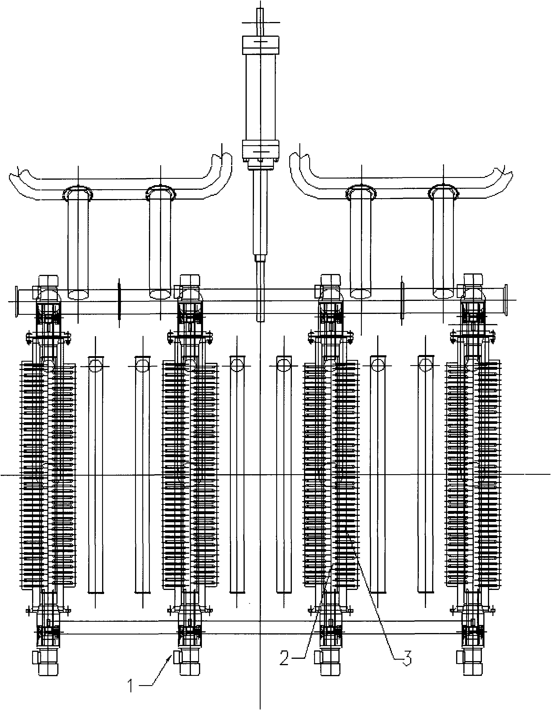
[0050] Such as image 3 As shown, the laminar flow width adjustable cooling device of the present invention is installed in the hot rolling and continuous rolling mill production line of the iron and steel enterprise, which includes several groups of nozzle devices 1 .

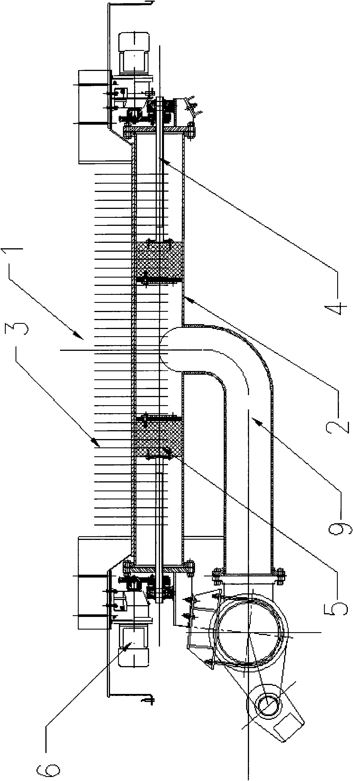
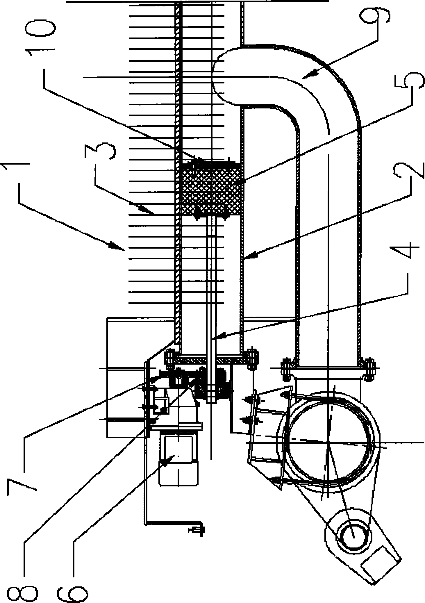
[0051] As shown in Figures 1 and 2, each group of nozzle devices 1 includes a manifold 2, several nozzles 3, two screw rods 4, two pistons 5, two motors 6, two large gears 7, two pinions 8, A water inlet pipe 9 and two grinding layers 10. The spray pipes 3 are evenly distributed on the top of the header 2, arranged in a staggered manner respectively, and extend downward along both sides of the header 2. A water inlet pipe 9 communicates with the middle part of the header pipe 2 top. Two screw rods 4 are respectively arranged in the center of both ends of the header 2 along the central axis of t...


PUM


Abstract

The invention provides a laminar flow width-offset-adjusting cooling device and a control method thereof. The laminar flow width-offset-adjusting cooling device comprises a plurality of groups of spray pipe devices, and each group of spray pipe device comprises a collecting pipe, two screw rods, two pistons and two motors, wherein the collecting pipe is provided with a plurality of evenly distributed spray pipes and a water inlet pipe; the two screw rods are respectively arranged at the two ends of the collecting pipe along the central axis of the collecting pipe, and can move inside the collecting pipe along the central axis of the collecting pipe; the two pistons are respectively positioned at the two adjacent ends of the screw rods, the external diameters of the pistons are matched with the internal diameter of the collecting pipe, the sides of the pistons are respectively provided with at least one locating key along the axial direction, and the at least one locating key is meshedwith at least one locating groove arranged on the inner wall of the collecting pipe along the axial direction; the two motors are respectively used for driving the screw rods; and the water inlet pipe is positioned in the middle of the collecting pipe. According to the requirements of the cooling technique of the strip steel with different widths, the invention can be used for adjusting the area of cooling water along the width direction of a channel, thus reducing the temperature reduction of the side of the strip steel, and ensuring the uniformity of the profile shape, the mechanical performance, the temperature and the phase change of the strip steel along the width direction.

Description

technical field [0001] The invention relates to a hot rolling laminar flow cooling technology in the field of metallurgy, in particular to a laminar flow width adjustable cooling device and a control method suitable for a metallurgical steel rolling production line. Background technique [0002] The laminar flow cooling device is used in the hot rolling and continuous rolling mill production lines of iron and steel enterprises. Its main function is to quickly cool the strip steel exported from finish rolling according to the target temperature set by coiling to ensure the product performance of the strip steel. [0003] Taking the hot rolling mill as an example, its laminar flow cooling device has a total of 76 sets of cooling headers (corresponding to one set of upper and lower). Among them, the first 68 groups are the main cooling section, and the last 8 groups are the refined cooling section. It is generally divided into several cooling zones, and each cooling zone has i...

Claims


Application Information

Patent Timeline
Patent Type & Authority Applications(China)
IPC IPC(8): B21B45/02B21B37/00B05B1/20B05B1/32B05B12/00
CPCB21B45/0218B21B45/0233B21B45/02
Inventor 王军李爱军孔德明李明王国平李华明林红钮国卫牟世学杨玉芳
Owner BAOSHAN IRON & STEEL CO LTD
Why Eureka
Try Eureka