Laminar flow cooling upper spray blocking device

A technology of laminar cooling and shielding plate, applied in the direction of spray device, spray device, workpiece surface treatment equipment, etc., can solve problems such as unfavorable production resource saving, reduction of temperature drop at the edge of strip steel, waste of cooling water, etc., to reduce temperature. The effect of reducing, ensuring the shape of the plate, and facilitating maintenance

Active Publication Date: 2012-03-28
BAOSHAN IRON & STEEL CO LTD
View PDF1 Cites 0 Cited by
  • Summary
  • Abstract
  • Description
  • Claims
  • Application Information

AI Technical Summary

Problems solved by technology

This method adopts the method for shielding the edge of the laminar flow cooling header, and provides a solution to the problem that the temperature of the edge of the strip is greatly reduced, but there are also shortcomings in this method. Obviously, the shortcoming of this prior art is that : When producing narrow strip steel, a large amount of cooling water is wasted in vain, which is not conducive to the saving of production resources
[0010] The inventor conceived to develop a laminar flow cooling upper spray shielding device, which can establish a gap laminar flow corresponding to the width of the strip channel according to the cooling process requirements of different widths of the strip, and realize the corresponding change in the width of the laminar flow cooling area. Thereby adjusting the area of ​​cooling water in the width direction of the channel, reducing the temperature drop at the edge of the strip, and ensuring the uniformity of the shape, mechanical properties, temperature and phase transition of the strip in the width direction; and the existing edge shielding technology Different, while achieving the same effect, it can also avoid the waste of cooling water resources. After online search, no identical or similar patented technology has been found so far.

Method used


Image

  • Laminar flow cooling upper spray blocking device
  • Laminar flow cooling upper spray blocking device
  • Laminar flow cooling upper spray blocking device

Examples


Embodiment 1

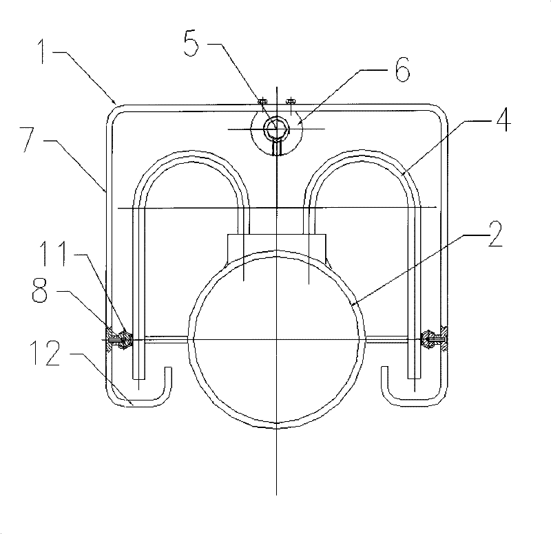
[0041] Such as figure 1 , 2As shown, a laminar flow cooling upper spray shielding device with a double-ended reverse screw mandrel of the present invention includes several groups of lower spray devices 1, and each group of lower spray devices 1 includes: a manifold 2 along the vertical The running direction of the strip steel is fixedly set by the header positioning seat 3. A plurality of goosenecks 4 are evenly distributed on each header 2 to connect with the upper part of the header 2, and extend downward along both sides of the header 2 respectively. A double-ended reverse screw rod 5 is erected on the top of the header pipe 2 along the length direction of the header pipe 2, and is connected with a motor 9, and the double-ended reverse screw rod 5 is driven to rotate by the motor 9. Both sliders 6 are provided with internal threads, which are respectively connected to the screw mandrel 5. The sliders 6 are respectively arranged on the threads at both ends of the double-e...

Embodiment 2

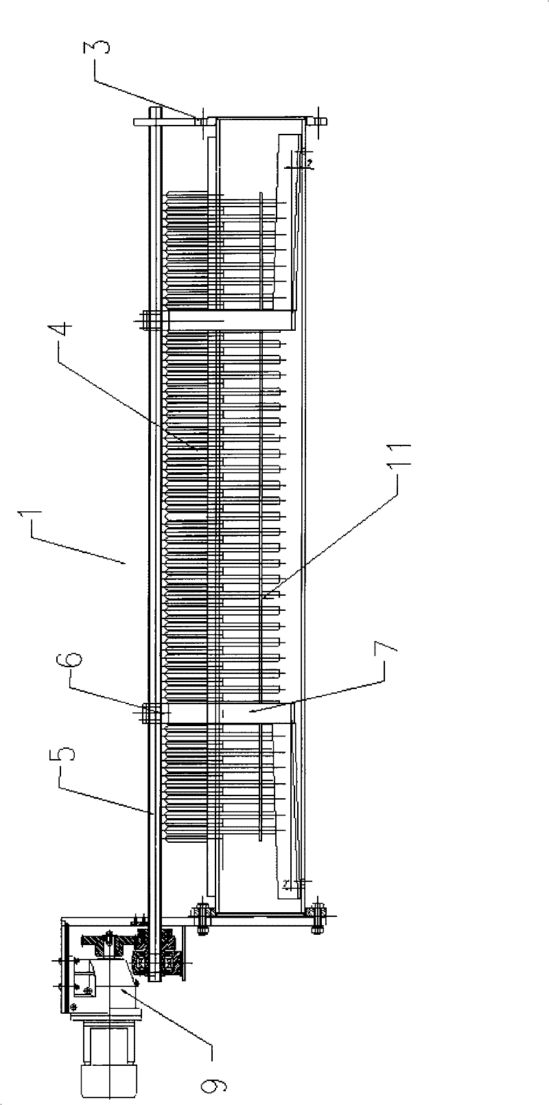
[0043] Such as figure 1 , 3 As shown, a laminar flow cooling upper spray shielding device with a double-ended reverse screw rod and a protective sleeve of the present invention includes several groups of lower spray devices 1, and each group of lower spray devices 1 includes: a manifold 2. It is fixedly arranged through the header positioning seat 3 along the vertical running direction of the strip steel. A plurality of goosenecks 4 are evenly distributed on each header 2 to connect with the upper part of the header 2, and extend downward along both sides of the header 2 respectively. A double-ended reverse screw rod 5 is erected on the top of the header pipe 2 along the length direction of the header pipe 2, and is connected with a motor 9, and the double-ended reverse screw rod 5 is driven to rotate by the motor 9. Both sliders 6 are provided with internal threads, which are respectively connected to the screw mandrel 5. The sliders 6 are respectively arranged on the threa...

Embodiment 3

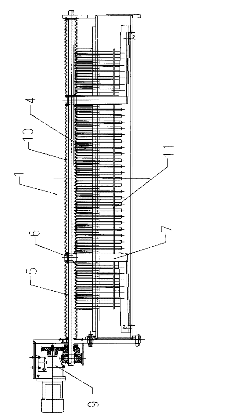
[0045] Such as figure 1 , 4 As shown, a laminar flow cooling upper spray shielding device with two double-headed reverse screw rods of the present invention includes several groups of lower spray devices 1, and each group of lower spray devices 1 includes: a manifold 2 along the The running direction of the vertical steel strip is fixedly set by the header positioning seat 3. A plurality of goosenecks 4 are evenly distributed on each header 2 to connect with the upper part of the header 2, and extend downward along both sides of the header 2 respectively. Two double-headed reverse screw rods 5 are erected coaxially on the upper part of the header pipe 2 along the length direction of the header pipe 2, connected with two motors 9, and the double-headed reverse screw rods 5 are driven to rotate by the motors 9. Both sliders 6 are provided with internal threads, which are respectively connected to the screw mandrels 5. The sliders 6 are respectively arranged on two double-ended...


PUM


Abstract

The invention relates to a laminar flow cooling upper spray blocking device which comprises a plurality of groups of lower spray devices, and each group of lower spray device comprises a collecting pipe, a plurality of spray pipes, at least one screw rod, two sliding blocks and two blocking plates, wherein the spray pipes are evenly distributed on the collecting pipes; the at least one screw rod is arranged at the upper part of the collecting pipe in a spanning way along the length direction of the collecting pipe; the two sliding blocks are provided with internal screw and are respectively connected with the screw rods by screw thread; the two blocking plates are respectively fixed with the sliding blocks, extend to an outlet of the collecting pipe; and the collecting pipe is movably shielded by a sliding mechanism. The laminar flow cooling upper spray blocking device can correspondingly build lower spray gap laminar flow corresponding to the width of a belt material channel according to the requirements of the cooling technique of the strip steel with different widths, and reduces the temperature reduction of the side of the strip steel by the corresponding change of a laminar flow cooling area along the width direction; and by adopting automatic lubrication, the device has the structure which is convenient for maintenance, and ensures the uniformity of the profile shape, the mechanical performance, the temperature and the phase change of the strip steel along the width direction.

Description

technical field [0001] The invention relates to a shielding device, in particular to a laminar cooling upper spray shielding device used in the hot rolling cooling process. Background technique [0002] The laminar flow cooling device is used in the hot rolling and continuous rolling mill production lines of iron and steel enterprises. Its main function is to quickly cool the strip steel exported from finish rolling according to the target temperature set by coiling to ensure the product performance of the strip steel. [0003] Taking the hot rolling mill as an example, its laminar flow cooling device has a total of 76 sets of cooling headers (corresponding to one set of upper and lower). Among them, the first 68 groups are the main cooling section, and the last 8 groups are the refined cooling section. It is generally divided into several cooling zones, and each cooling zone has its own main cooling section and the cooling section of the fine cooling section connected in s...

Claims


Application Information

Patent Timeline
Patent Type & Authority Patents(China)
IPC IPC(8): B21B45/02B05B1/28B05B1/20B05B15/04
Inventor 王军
Owner BAOSHAN IRON & STEEL CO LTD
Why Eureka
Try Eureka