Disc-shaped cutting tool

A disc-shaped, tool technology, applied in milling cutters, manufacturing tools, metal processing equipment, etc., can solve problems such as ineffective chip breaking, and achieve the effect of improving chip breaking performance, improving grades, and making products more beautiful

Inactive Publication Date: 2010-11-24
CHENGDU TOOL RES INST
View PDF6 Cites 4 Cited by
  • Summary
  • Abstract
  • Description
  • Claims
  • Application Information

AI Technical Summary

Problems solved by technology

The part of the straight line L constitutes the rake face of the tool, and the part of the straight line L' constitutes the anti-chip surface of the tool. This groove type is a simple two-dimensional groove type, which cannot solve the problem of effective chip breaking in actual production

Method used


Image

  • Disc-shaped cutting tool
  • Disc-shaped cutting tool
  • Disc-shaped cutting tool

Examples


Embodiment Construction

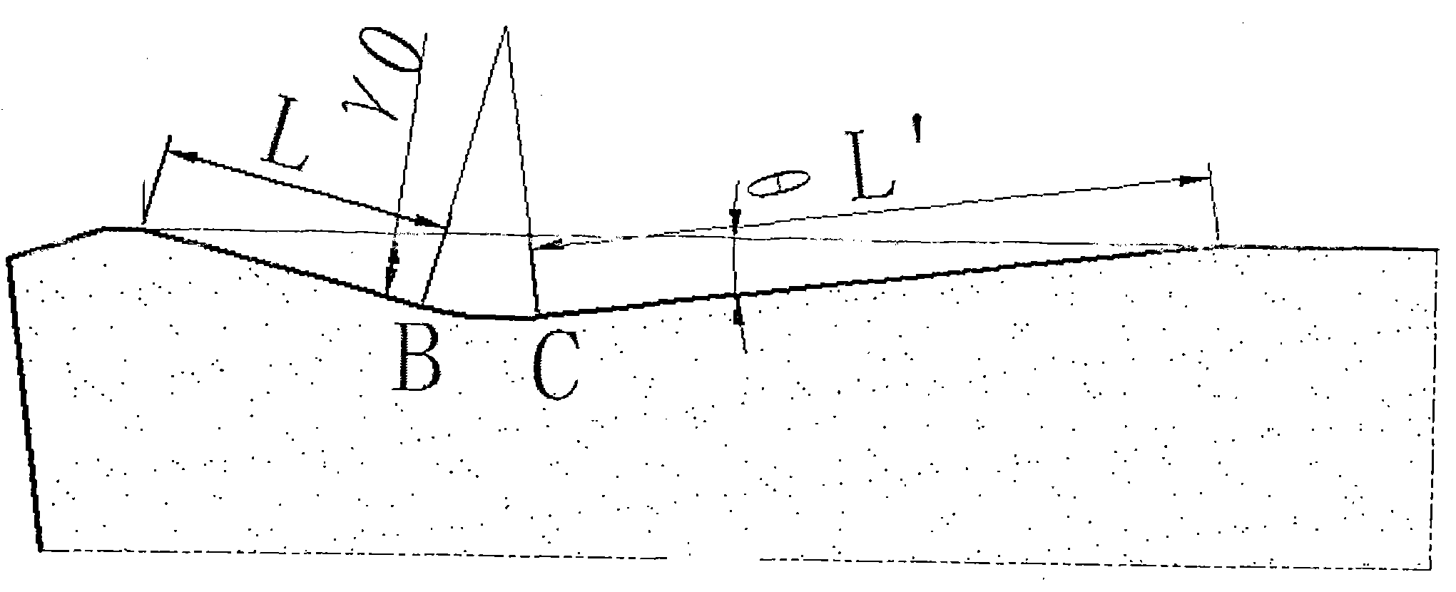
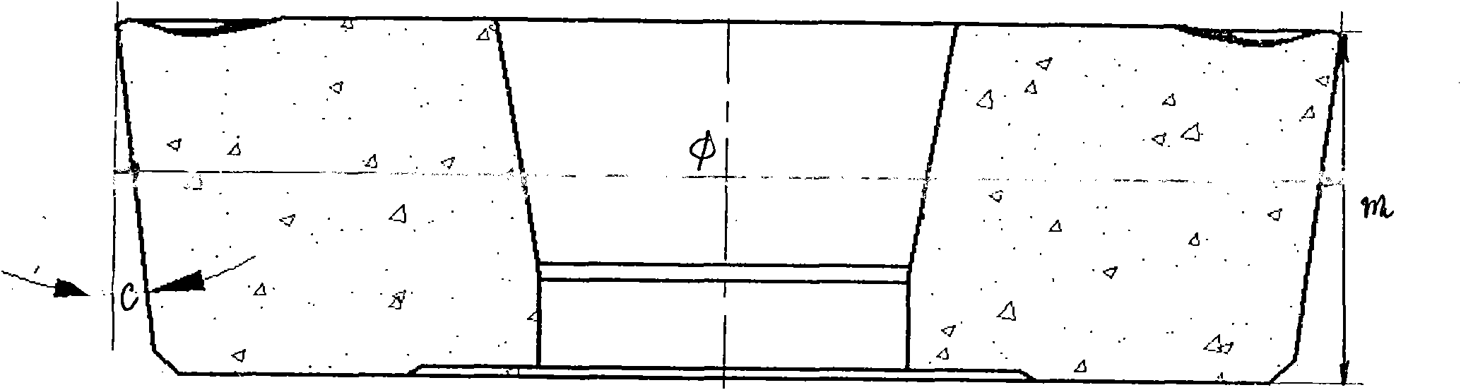
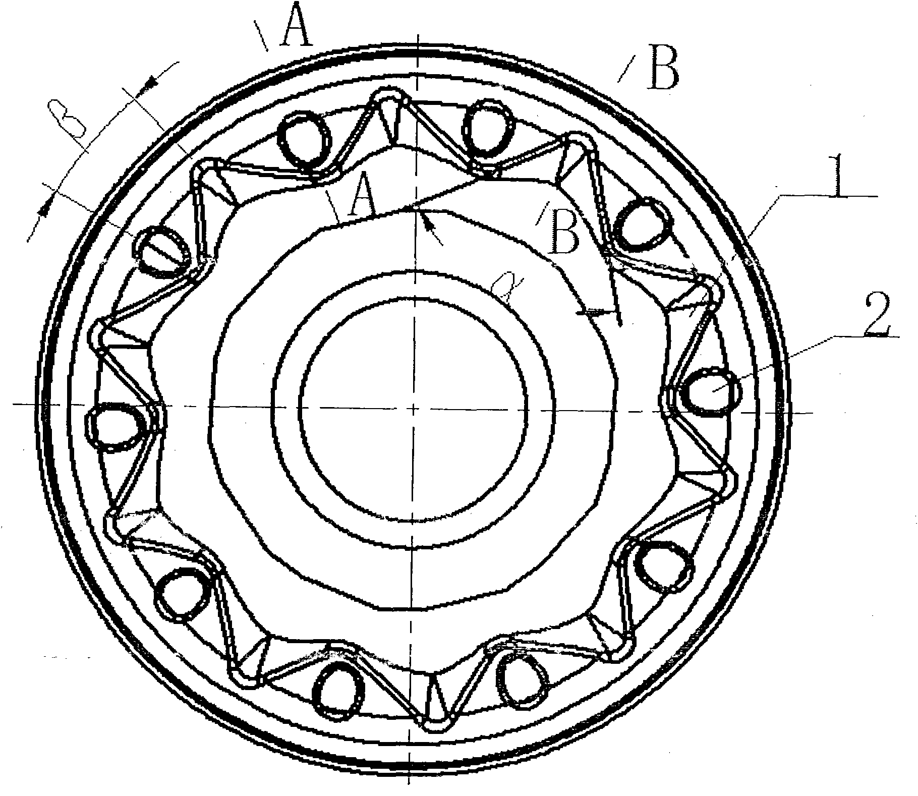
[0022] The outer circle of the tool of the present invention is φ32mm, the tool tip height m is 9.52mm, and the relief angle c is 7°. The angle γ0 between the rake face and the front face is 17°, the angle θ between the anti-chip face and the rear face is 10°, the distance between the front and rear faces is 0.15mm, and 10 bosses 1 are evenly distributed on the anti-chip face. The stages are connected to form a ring-shaped 10-point star block. The cone angle of the boss is α=78, 3°. There is a spherical crown-shaped bump 2 on the anti-chip surface of the triangle area between two adjacent cone angles. The projection of the bump 2 on the triangular area occupies one third of the area of ​​the triangular area. The distance between the apex of the bump 2 and the anti-chip surface is 0.2 mm, and the distance between the apex of the boss 1 and the anti-chip surface is 0.3 mm. The angle β between the vertex of the taper angle of the bump 1 and the vertex of the bump 2 and the tool...


PUM


Abstract

The invention provides a disc-shaped cutting tool, which solves the problem of poor chip breaking performance of conventional cutting tools. A chip breaker groove consists of a front tool face, a circular surface and a reverse chip surface, wherein the front tool face and the reverse chip surface are coaxial conical surfaces and are in tangential connection with the circular surface; an included angle gamma0 between the front tool face and a front end face is 15 to 17 DEG; an included angle theta between the reverse chip surface and the rear end face is 15 to 17 DEG; a rear end face is 0.1 to 0.2mm higher than the front end face, namely the height h of a cutting edge is 0.1 to 0.2mm; a plurality of bosses (1) are uniformly distributed on the coaxial periphery of the reverse chip surface; and bumps (2) are arranged between every two adjacent bosses.

Description

Technical field: [0001] The invention relates to a circular tool which is mainly used for processing train wheels and other discs or shaft parts. Background technique: [0002] For a long time in the processing of train wheels, there has been a disadvantage that iron filings continue to wrap around the toolholder iron filings during the processing process. The wound iron filings affect the surface quality (surface finish) of the hub. In severe cases, processing accidents may damage the machine tool and may harm the processing workers. Of personal safety. Therefore, during the processing, workers must use tools (such as iron hooks) to forcibly remove the entangled iron filings, which increases the labor intensity of the workers and also poses a certain personal safety hazard to the workers because the machine tool is on. [0003] The original blade structure is like figure 1 , The chip breaker of the insert is a typical two-dimensional geometry, consisting of a straight line L, an ...

Claims


Application Information

Patent Timeline
Patent Type & Authority Applications(China)
IPC IPC(8): B23C5/06
Inventor 杨启坤袁宏辉余航梁佳佳
Owner CHENGDU TOOL RES INST
Why Eureka
Try Eureka