Vibration chip breaking device and lathe

A technology of chip breaking and vibrating wheel, which is applied to lathe tools, turning equipment, accessories of tool holders, etc., which can solve the problems that chips cannot be broken and affect the processing of workpieces, etc.

Active Publication Date: 2021-05-11
AKEMET (JIANGSU) FLUID CONTROL SYST CO LTD
View PDF12 Cites 0 Cited by
  • Summary
  • Abstract
  • Description
  • Claims
  • Application Information

AI Technical Summary

Problems solved by technology

[0003] The traditional chip breaking structure breaks the chip by periodically changing the chip angle, but there are still some chips that cannot be broken, which affects the processing of the workpiece; therefore, for those skilled in the art, how to improve the probability of chip breaking is Current technical issues to be resolved

Method used


Image

  • Vibration chip breaking device and lathe

Examples


Embodiment Construction

[0023] The core of the present invention is to provide a vibrating chip breaking device, which can effectively improve chip breaking efficiency of chips.

[0024] In order to enable those skilled in the art to better understand the technical solution of the present invention, the vibrating chip breaking device and the lathe of the present invention will be described in detail below in conjunction with the accompanying drawings and specific implementation methods.

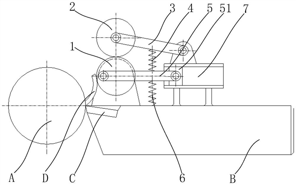
[0025] Such as figure 1 As shown, it is a schematic structural diagram of the vibrating chip breaking device provided by the present invention; in the figure, A represents the workpiece being turned, B represents the tool handle, C represents the cutting edge, the cutting edge is installed on the tool handle, and D represents chips; the vibrating chip breaking device Including friction roller 1, vibration wheel 2, swing rod 3, vibration spring 4 and other structures, wherein friction roller 1 is rotatably arranged o...


PUM


Abstract

The invention discloses a vibrating chip breaking device. The frictional force of chips generated from a workpiece drives the friction roller to rotate; the vibration wheel is arranged above the friction roller, and the distances between the outer periphery of the friction roller and the rotating shaft are different, and the friction roller drives the vibration wheel up and down. Ups and downs; one end of the swing rod is connected to the vibration wheel, so that the vibration wheel swings around the hinge shaft at the other end; one end of the vibration spring is connected to the swing rod, and the other end is supported by the handle, and the vibration spring provides upward elastic force to the vibration rod to maintain the movement of the vibration wheel ;Because the distance between the circumference of the friction roller and the rotating shaft is not equal, the distance between the friction roller and the workpiece changes periodically during the rotation of the friction roller, which changes the angle of the chip, which is beneficial to aggravate the plastic deformation of the chip, and the vibration wheel periodically The eccentric roller is vibrated to increase the deformation and breaking probability of chips, improve the effect of chip breaking, and make chips easier to break. The lathe of the present invention can achieve the same technical effect.

Description

technical field [0001] The invention relates to the technical field of mechanical processing, and further relates to a vibrating chip breaking device. Furthermore, the invention also relates to a lathe. Background technique [0002] During turning, the workpiece to be processed rotates at high speed, and the cutting edge contacts the workpiece to form the required shape. A large amount of chips are generated during the processing, and the chips need to be broken off in time, otherwise the normal chip removal process will be affected; Take appropriate measures to control the curling, outflow and breaking of chips in order to ensure the normal processing. [0003] The traditional chip breaking structure breaks the chip by periodically changing the chip angle, but there are still some chips that cannot be broken, which affects the processing of the workpiece; therefore, for those skilled in the art, how to improve the probability of chip breaking is Current technical issues t...

Claims


Application Information

Patent Timeline
Patent Type & Authority Patents(China)
IPC IPC(8): B23B27/22
CPCB23B27/22
Inventor 郭彩芬
Owner AKEMET (JIANGSU) FLUID CONTROL SYST CO LTD
Why Eureka
Try Eureka