Integrated DIN rail attachment feature for superior attachment

A track, connected to the technology, applied in the direction of electrical components, substation / switch layout details, support structure installation, etc., can solve the problem of not providing redundant latches, etc.

Inactive Publication Date: 2010-12-22
ROCKWELL AUTOMATION TECH
View PDF6 Cites 17 Cited by
  • Summary
  • Abstract
  • Description
  • Claims
  • Application Information

AI Technical Summary

Problems solved by technology

These existing attachment parts described above did not provide adequate redundant latching, did not provide sufficient resistance to unlatching in harsh conditions, and / or were otherwise considered suboptimal

Method used


Image

  • Integrated DIN rail attachment feature for superior attachment
  • Integrated DIN rail attachment feature for superior attachment
  • Integrated DIN rail attachment feature for superior attachment

Examples


Embodiment Construction

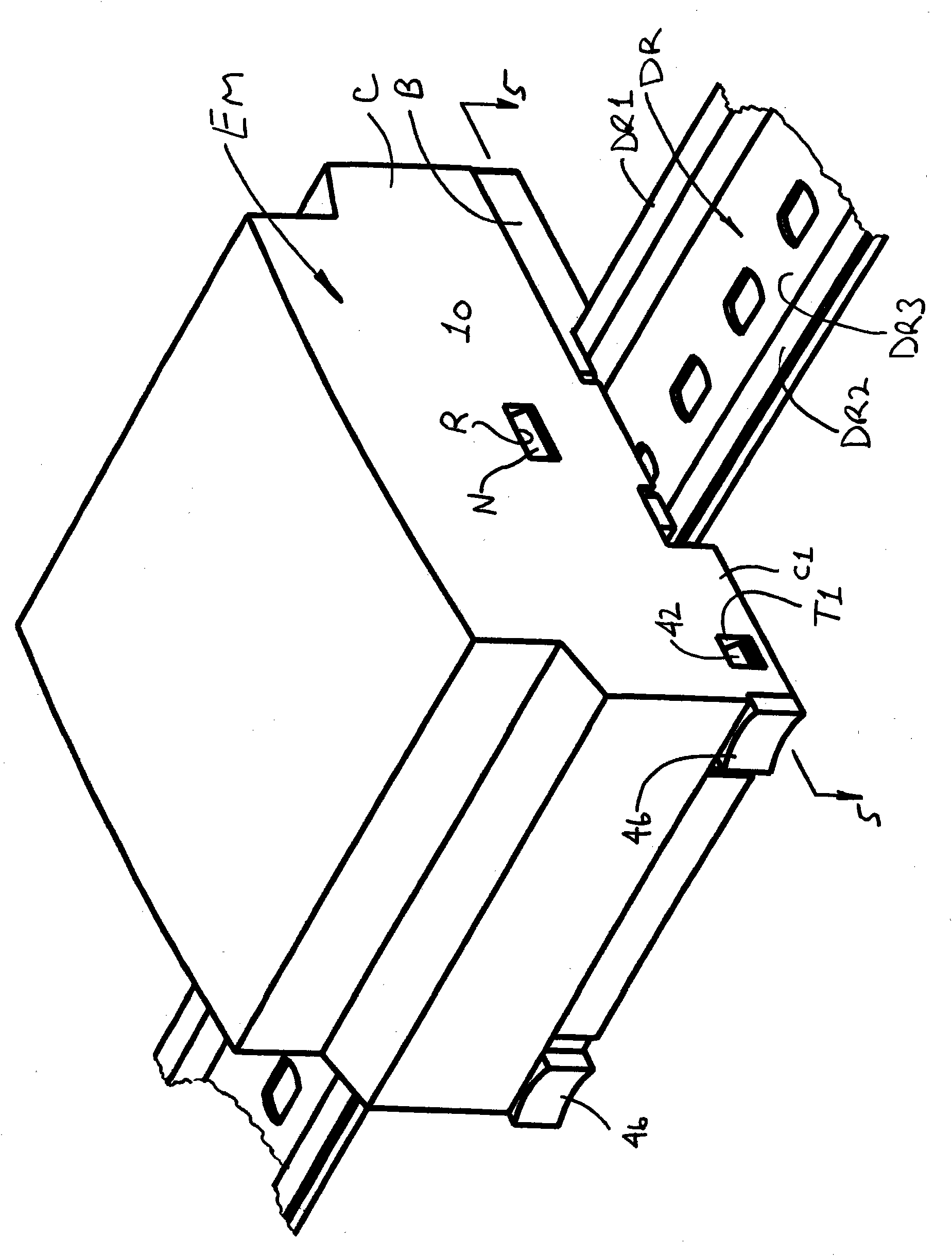
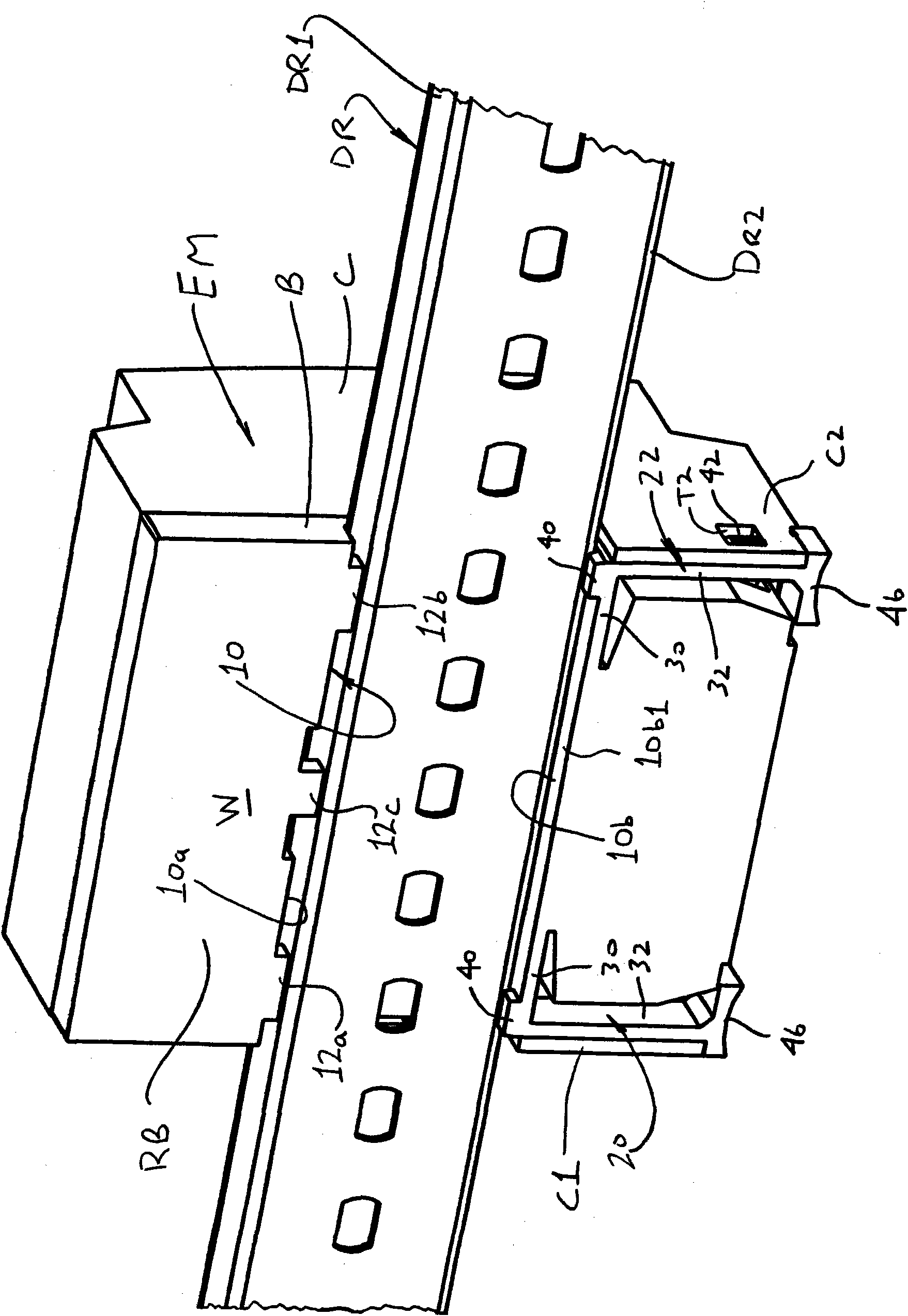
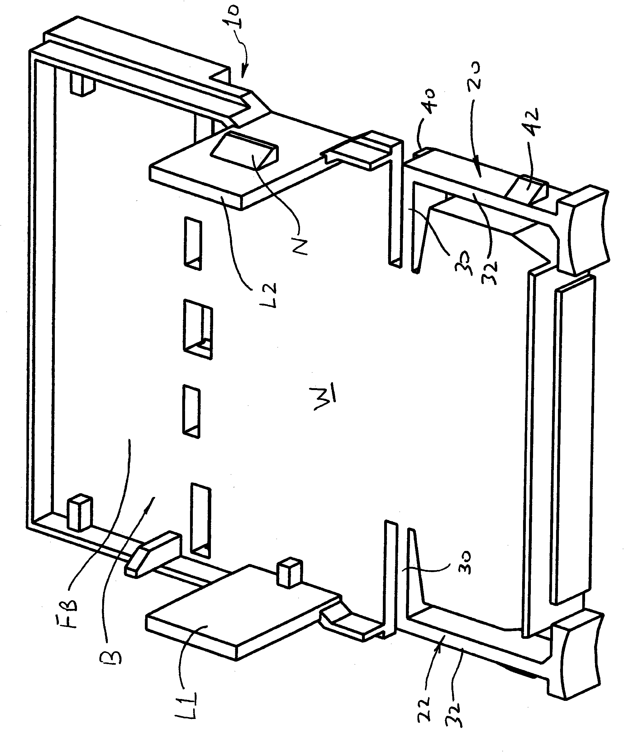
[0013] figure 1 A conventional DIN rail mounting structure DR is shown, which includes first and second flanges DR1, DR2 connected to opposite sides of the recessed central portion DR3. The electronic module EM includes the DIN rail attachment part according to the present invention, wherein the DIN rail attachment part provides a means for releasably connecting the module EM to the DIN rail DR. Combined with the rear view figure 2 , The electronic module EM includes: a base B for supporting one or more electronic circuit boards or other electronic components, and a cover C connected to the base B for sealing the electronic components connected to the base B. In the example, base B (in Figure 3A with Figure 3B Shown in) includes first and second legs L1, L2, which are accommodated in the cover C, and respectively include a clamping part that engages with the mating hole of the cover C or other regions R through a releasable snap fit N.

[0014] See also Figure 3A , 3B, 4A, 4...


PUM


Abstract

An electronics module includes a base and a cover connected to the base. The base includes a recess adapted to receive an associated mounting rail. At least one fixed rail constraining tab is located adjacent a first edge of the recess and is adapted to engage a first flange of the associated mounting rail. First and / or second latch arms are located adjacent a second edge of the recess that is opposite the first edge of the recess. The first and second latch arms are connected to a fixed portion of the second edge and project outwardly relative to opposite lateral sides of the fixed portion. Each of the first and second latch arms includes a rail capture tab. The first and second latch arms are selectively movable resiliently to and from latched and unlatched positions, wherein the rail capture tabs of the first and second latch arms project beyond the fixed portion of the second edge and into the recess when the first and second latch arms are located in their respective latched positions, and wherein the rail capture tabs of the first and second latch arms are withdrawn relative to the fixed portion of the second edge when the first and second latch arms are located in their respective unlatched positions. The cover or other portion of the module defines first and second receiving locations that receive and retain portions of the first and second latch arms when the first and second latch arms are located in their respective latched positions.

Description

Technical field [0001] The present invention relates to an electronic module with attachment parts, and in particular to an integrated DIN rail attachment part for good attachment. Background technique [0002] It is known to provide an electronic module with attachment parts for releasably fixing the module on a DIN rail, which is an industry standard mounting structure. Known DIN rail attachment parts include one or more latches, which are manufactured to be separated from the electronic module and movably connected to the module. After being assembled to the module, this latch can be used in the unlocking position for connecting / disconnecting the module to the DIN rail and the latch for fixing the module to the DIN rail immovably The positions are manually slid or moved. This type of attachment part is usually effective, but one or more latches need to be separately constructed (for example, injection molded) and then assembled on the module, which increases product cost. I...

Claims


Application Information

Patent Timeline
Patent Type & Authority Applications(China)
IPC IPC(8): H05K7/14H05K7/18
CPCH02B1/052
Inventor 纳森·J·莫尔纳道格拉斯·R·博德曼
Owner ROCKWELL AUTOMATION TECH
Why Eureka
Try Eureka