Timepiece

A technology for clocks and clock movements, applied in the field of clocks, can solve the problems of impossible to fit gears, difficult to assemble, heavy and so on

Active Publication Date: 2011-01-26
ROLEX SA
View PDF7 Cites 4 Cited by
  • Summary
  • Abstract
  • Description
  • Claims
  • Application Information

AI Technical Summary

Problems solved by technology

This kind of mechanism is complicated, heavy and difficult to assemble, and can only be used to correct the distance between large shafts
They are not suitable for small inter-shaft distances where it is impossible to fit gears

Method used


Image

  • Timepiece
  • Timepiece
  • Timepiece

Examples


Embodiment Construction

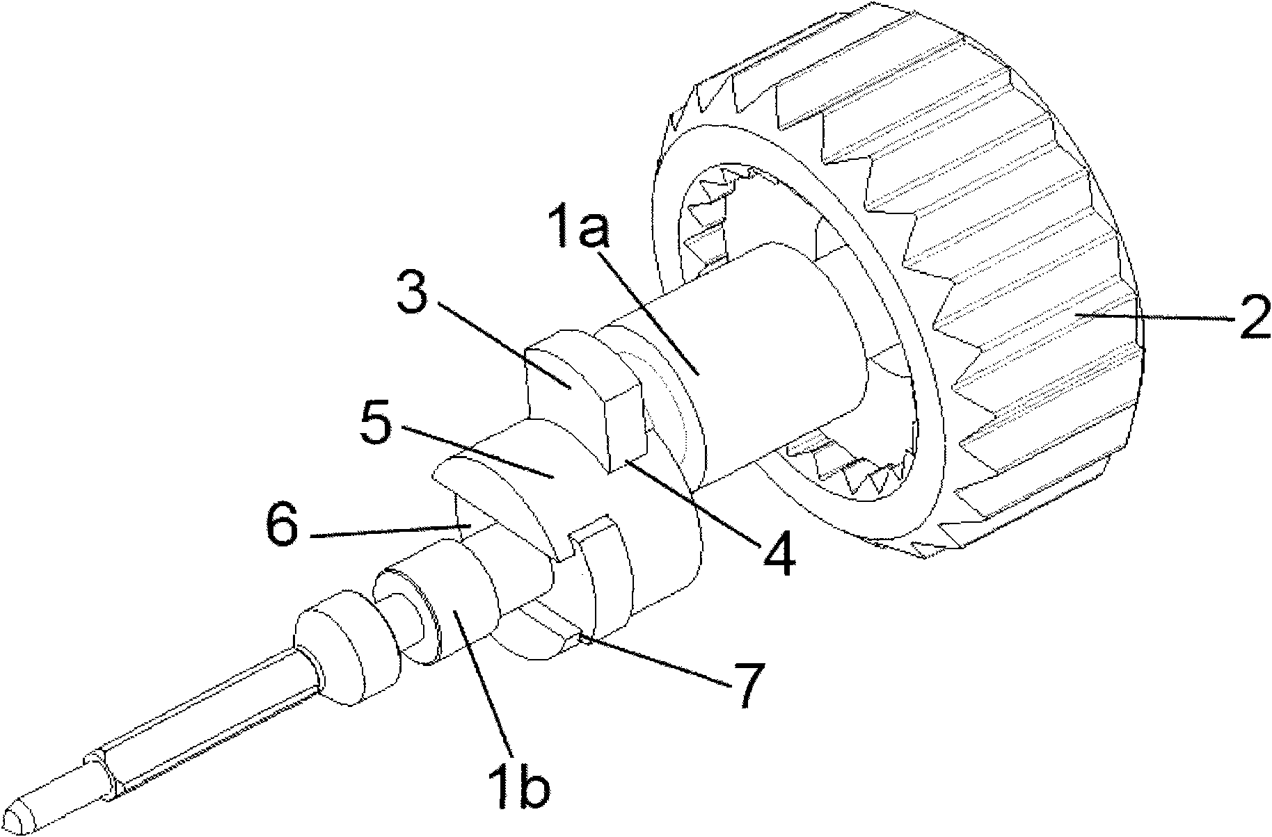
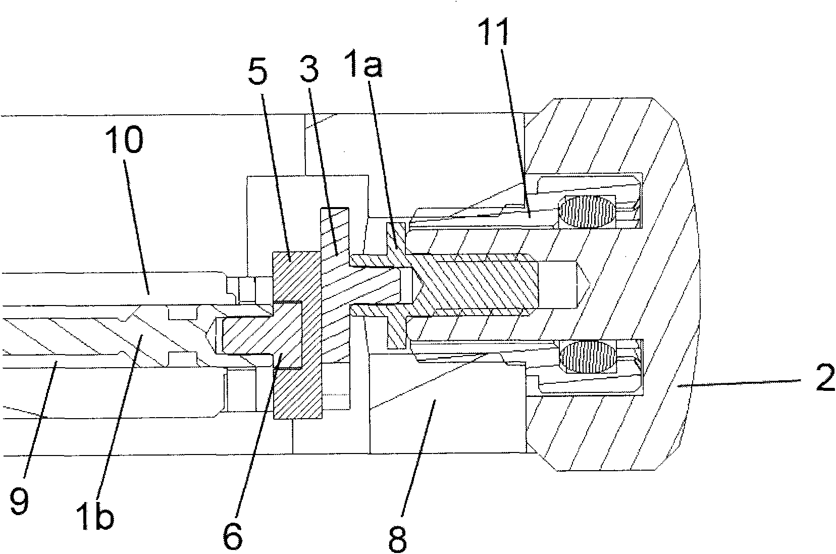
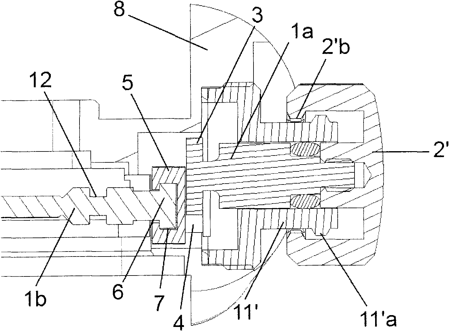
[0015] figure 1 The transmission mechanism shown has two parallel-axis bull cores 1a and 1b. One end of the caliber 1a is connected to the central arbor (not shown in the figure) designed to drive the crown 2 on the outside of the case. The other end of the hub 1a is connected to a sliding member 3 engaged in a slide rail 4 formed in one surface of the link 5 and extending perpendicular to the axis of the hub 1a.

[0016] One end of the hub 1b adjacent to the hub 1a is connected to a sliding member 6 engaged in a slide rail 7 formed on the other surface of the connecting rod 5 and also extending perpendicular to the axis of the hub 1b. Since the two cores 1a and 1b are parallel, the two slide rails 4 and 7 are also parallel. However, the orientation of these slide rails 4 and 7 is perpendicular to each other. In order to allow sliding between the sliding element and the respective sliding rail, the cross-section of the sliding element and the respective sliding rail are com...


PUM


Abstract

This timepiece comprises a case (8) enclosing a horological movement (10), and a transmission mechanism for transmitting constant-velocity rotary movements between two stems (1a, 1b) on parallel axes, connecting the outside of the case (8) to the horological movement (10) through a hole in the case (8). The adjacent ends of these two stems (1a, 1b) are connected to two respective sliding elements (3, 6) having defined cross sections engaged with two respective slide-ways (4, 7) having cross sections complementary to those of said sliding elements, having sliding planes perpendicular to said axes, the two slide-ways (4, 7) being connected to a common linking member (5) and being oriented at an angle of 90 DEG to each other.

Description

technical field [0001] The invention relates to a timepiece, comprising a case enclosing the movement of the timepiece and a transmission mechanism for transmitting constant-speed rotary motion between two cores on approximately parallel axes, the case is connected through a hole in the case The outer part of the body is connected to the watch movement, in which the adjacent ends of the two cores are connected to two corresponding sliding elements, which have defined a section and engage with two corresponding slide rails, the slide rails Having a section complementary to that of the sliding element, and oriented at an angle of 90° to each other, the two sliding rails are connected to a common link. Background technique [0002] This transmission mechanism is disclosed in CH36526. The mechanism does not define a sliding surface. [0003] There are many different reasons why the crown movement of the transmission mechanism used to transmit the rotary movement is positioned ...

Claims


Application Information

Patent Timeline
Patent Type & Authority Applications(China)
IPC IPC(8): G04B37/06
CPCG04B37/066
Inventor 弗拉维安·克雷斯曼吕多维克·兹比吕特
Owner ROLEX SA
Why Eureka
Try Eureka