Composite heat exchanger end structure

A technology of heat exchanger and end structure, which is applied in the direction of heat exchange equipment, heat exchanger shell, indirect heat exchanger, etc., and can solve problems such as difficult sealing

Inactive Publication Date: 2013-04-10
CATERPILLAR INC
View PDF1 Cites 0 Cited by
  • Summary
  • Abstract
  • Description
  • Claims
  • Application Information

AI Technical Summary

Problems solved by technology

However, sealing may become more difficult as internal pressure and / or spacing increases

Method used


Image

  • Composite heat exchanger end structure
  • Composite heat exchanger end structure
  • Composite heat exchanger end structure

Examples


Embodiment Construction

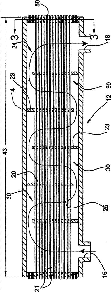
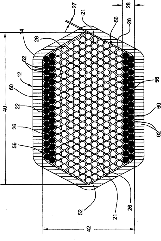
[0012] The present disclosure relates to a heat exchanger having a bundle of tubes disposed within a housing with resilient end structures at least partially spanning a heat exchange chamber disposed in compressed, plug-forming relationship . The resilient end structure includes one or more boundary segments extending between the inner wall of the shell and the perimeter of the tube bundle. The boundary segment comprises a combination of materials having different compressive properties that provide enhanced support to the boundary segment.

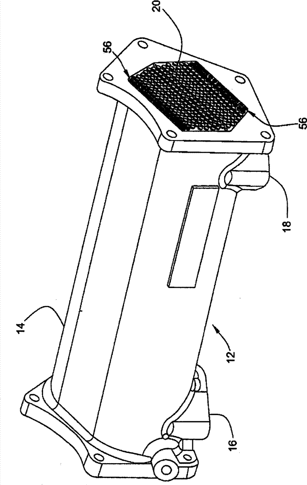
[0013] Reference will now be made to the drawings, wherein like reference numerals represent like elements throughout the several views. figure 1 An exemplary heat exchanger 12 is shown, such as an oil cooler or the like. In this regard, it should be understood that although heat exchanger 12 is shown in the form of an oil cooler such as may be used on an internal combustion engine, heat exchanger 12 is in no way limited to this configu...


PUM


Abstract

A heat exchanger having a tube bundle disposed within a housing with a resilient end structure disposed in compressed, plug-forming relation at least partially across the heat exchanging cavity. The resilient end structure includes one or more boundary segments extending between an internal wall of the housing and the perimeter of the tube bundle. The boundary segment includes a combination of materials having differing compression characteristics providing enhanced support to the boundary segments.

Description

technical field [0001] The disclosure of this patent relates generally to heat exchangers, and more particularly to heat exchangers that incorporate resilient end structures that hermetically enclose the heat exchanger adapted to extend along the length of the tube bundle Provides a transition zone for reverse flow. Background technique [0002] Heat exchangers are used in a variety of applications and can come in many different forms. By way of example only, oil coolers for internal combustion engines typically take the form of an elongated housing surrounding a tube bundle of substantially discrete heat exchanger tubes. The tubes are usually stacked in a generally hexagonal pattern such that each tube is surrounded by up to six other tubes. Of course, other patterns may also be utilized. The tube bundles are mounted through heat conducting fins and / or flow guide baffles, and may be supported by baffles and heat conducting fins disposed within the housing to form a meand...

Claims


Application Information

Patent Timeline
Patent Type & Authority Patents(China)
IPC IPC(8): F28D7/00F28D7/10F28D7/08F28F1/00
CPCF28F2255/02F28F21/067F28F9/005F28F9/02F28D7/1607F28D7/163F28D7/00F28D7/10F28F1/00Y10T29/49826
Inventor S·I·马修D·J·贝克尔T·J·格拉本斯泰特D·A·皮特尔斯基W·E·多沃凡S·M·伯特兰德
Owner CATERPILLAR INC
Why Eureka
Try Eureka