Supercharge Your Innovation With Domain-Expert AI Agents!

Method for automatically controlling an internal combustion engine

一种内燃机、旋转角度的技术,应用在内燃活塞发动机、阀控制、电子控制等方向,达到省去机械控制的效果

Inactive Publication Date: 2011-03-30
MTU FRIEDRICHSHAFEN GMBH
View PDF11 Cites 0 Cited by
  • Summary
  • Abstract
  • Description
  • Claims
  • Application Information

AI Technical Summary

Problems solved by technology

Then, the non-defective valve rotator needs to be replaced

Method used


Image

  • Method for automatically controlling an internal combustion engine
  • Method for automatically controlling an internal combustion engine
  • Method for automatically controlling an internal combustion engine

Examples


Embodiment Construction

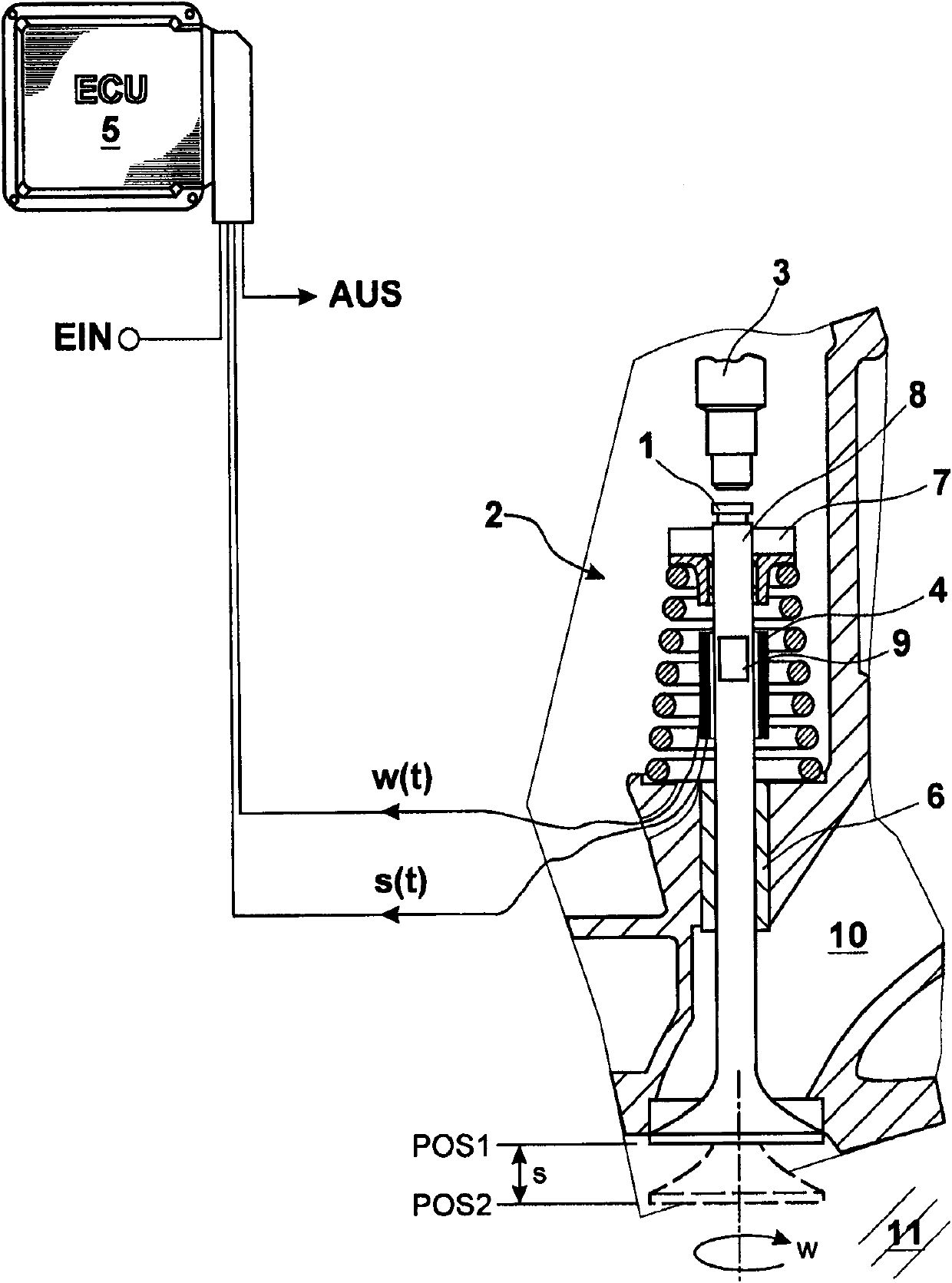
[0028] figure 1 Shows a system diagram with a combined sensor for travel and angle of rotation measurement at the gas exchange valve 1 . The components shown are: a gas exchange valve 1 , eg an exhaust valve, a cylinder head 2 , a rocker arm 3 for actuating the gas exchange valve 1 , a sensor 4 and an electronic control unit 5 (ECU). The gas exchange valve 1 is inserted into the cylinder head 2 via a guide tube 6 and is actuated via a rocker arm 3 . By means of the swivel device 7 , the gas exchange valve 1 is simultaneously rotated through an angle during actuation, whereby deposits on the gas exchange valve 1 are prevented. In the first position POS1 the gas exchange valve 1 completely closes the combustion chamber 11 . In the second position POS2 , the gas exchange valve 1 opens the passage from the combustion chamber 11 to the exhaust tract 10 , through which passage the exhaust gas then flows, for example, to the exhaust gas turbocharger. The sensor 4 simultaneously de...


PUM


Abstract

The present invention relates to a method for automatically controlling an internal combustion engine, in which an axial displacement (s(t)) and an angle of rotation (w(t)) of a gas-exchange valve are measured during a valve stroke. A displacement deviation is computed from the displacement (s(t)) relative to a reference valve, and an angle of rotation deviation is computed from an initial value and an end value of the angle or rotation. The further operation of the internal combustion engine is set on the basis of the displacement deviation and the angle of rotation deviation.

Description

technical field [0001] The invention relates to a method for controlling and regulating an internal combustion engine, in which method the axial travel (Weg) and the rotational angle (Verdrehwinkel) of a gas exchange valve are measured continuously. Background technique [0002] In practice large diesel engines without automatic valve play compensation are offered. Therefore, after a fixed predetermined operating time, the valve play must be adjusted by the service mechanic in accordance with the maintenance plan. In the maintenance plan, boundary conditions (for example, coolant temperature less than 40° C.) are shown along with detailed steps. First, the rotary device is placed, the cylinder head cover is removed, and the gas exchange valves are sequentially brought into the closed state by means of the rotary device. Then, in the closed state, check the corresponding actual valve clearance by means of a gauge. If the actual valve clearance deviates from the theoretical...

Claims


Application Information

Patent Timeline
Patent Type & Authority Applications(China)
IPC IPC(8): F02D13/02G01B7/30
CPCF01L2800/11F02D13/02F01L13/0005F01L2800/17F01L2820/045F01L1/32F01L2201/00Y02T10/18Y02T10/12Y10T137/8242
Inventor M·赫勒H·弗兰克M·威尔曼
Owner MTU FRIEDRICHSHAFEN GMBH
Features
  • R&D
  • Intellectual Property
  • Life Sciences
  • Materials
  • Tech Scout
  • Unparalleled Data Quality
  • Higher Quality Content
  • 60% Fewer Hallucinations
Learn More