Supercharge Your Innovation With Domain-Expert AI Agents!

Slot part forming method for pipe

A technology for pipes and grooves, which is applied in the field of groove forming of pipes and can solve problems such as difficult-to-form grooves

Inactive Publication Date: 2011-05-04
有限会社小田技商 +1
View PDF10 Cites 0 Cited by
  • Summary
  • Abstract
  • Description
  • Claims
  • Application Information

AI Technical Summary

Problems solved by technology

Therefore, it is necessary to additionally form the grooves 11, 12 deeply into the R shape in advance, but as described above, it is difficult to form the grooves 11, 12 deeply in the thin-walled pipe material 10.

Method used


Image

  • Slot part forming method for pipe
  • Slot part forming method for pipe
  • Slot part forming method for pipe

Examples


no. 1 approach

[0096] refer to Figure 1 to Figure 5 , the groove portion forming method of the pipe material 60 according to the first embodiment of the present invention will be described.

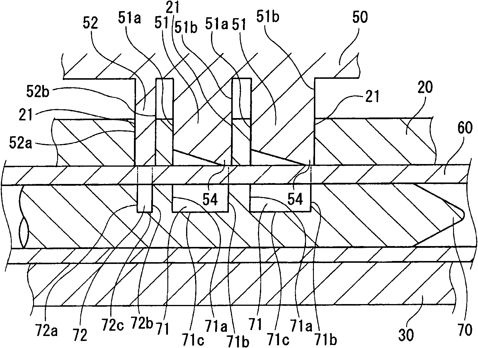
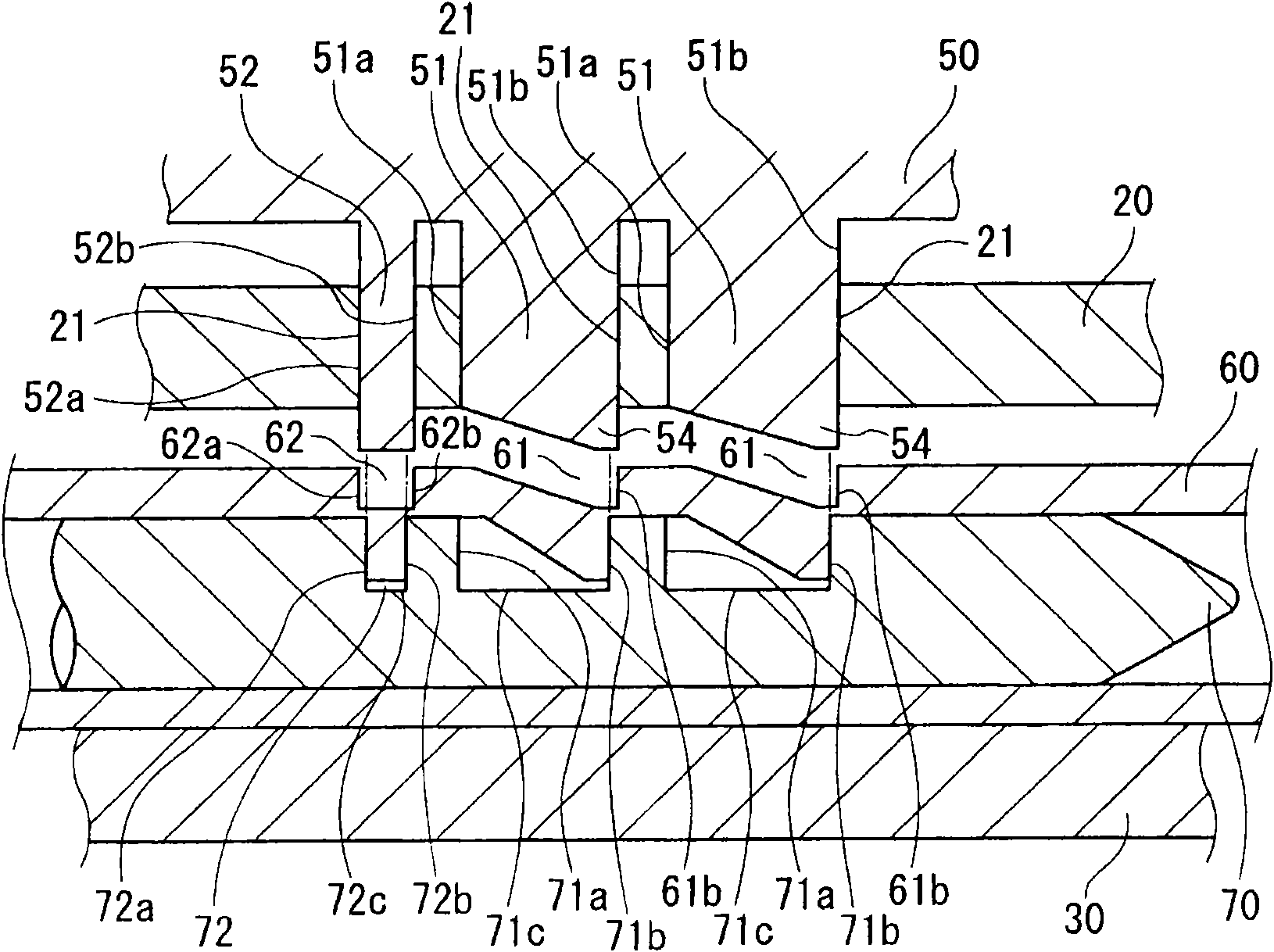
[0097] In this groove forming method of the pipe material 60 , the pipe material 60 and a die for punching the pipe material 60 are used. Furthermore, the die includes an upper die 20 , a lower die 30 , a female die 70 , and a male die 50 corresponding to the female die 70 , and is characterized by the positional relationship between the female die 70 and the male die 50 .

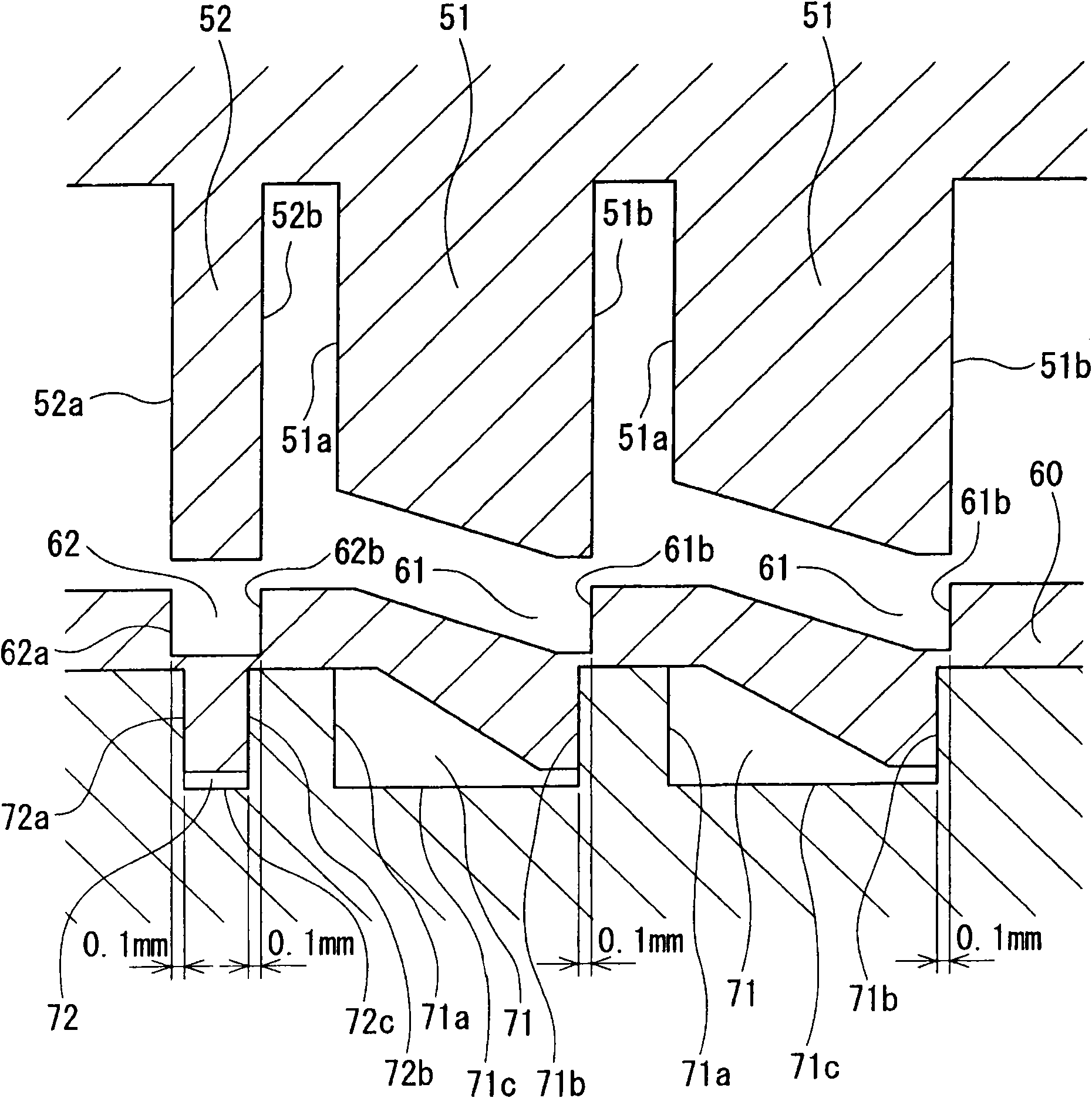
[0098] The tubing 60 is composed of Figure 14 The part of the foot of the headrest of the motor vehicle shown has a wall thickness of 1.5 mm. Further, two types of groove portions, namely, an inclined groove 61 and a rectangular groove 62 are formed in the headrest pipe material 60 .

[0099] The inclined groove 61 is a groove whose right inner wall 61b is perpendicular to the axial direction of the headrest pipe material 60 an...

no. 2 approach

[0119] Next, refer to Figure 7 and Figure 8 , the groove portion forming method of the pipe material 60 according to the second embodiment of the present invention will be described. In addition, the same code|symbol is attached|subjected to the same part as 1st Embodiment.

[0120] The difference between this embodiment and the first embodiment lies in the press-in blades 81, 82 of the male die 80 and the part of the accompanying die, and other structural elements are the same as those of the first embodiment.

[0121] Between the upper mold 20 and the male mold 80, and between the upper mold 20 and the lower mold 30, coil springs 90, 91 are provided as buffer members, respectively.

[0122] The male die 80 has a first press-in edge 82 corresponding to the recessed portion 72 and a second press-in edge 81 corresponding to the wide recessed portion 71 . Here, the first press-in blade 82 of the male die 80 is a short cylindrical cylindrical blade 82 rotatably attached arou...


PUM


Abstract

The present invention provides a slot part forming method for pipe, thereby forming the slot part with a mode that a R shape at the upper end of the inner wall is smaller and an actual slot depth can be increased. The forming method is used for forming slots (61,62) on an outer peripheral surface of the pipe (60) for headrest. A first pressing edge is a rectangular edge (52) in which a left side surface and a right side surface (52a,52b) are vertical with an axial direction and a width in a left-and-right direction is larger than the width between a left inner wall and a right inner wall (72a,72b) of a dent part (72). Furthermore a second pressing edge is an inclined edge (51) which has a right side surface (51b) that is vertical with the axial direction. Furthermore, the depths of the dent part (72) and a large width dent part (71) are formed so an inner circumferential surface of the pipe (60) for headrest does not contact with the bottom surfaces (72c,71c) of the dent part (72) and the large width dent part (71). When the left side surface and the right surface (52a,52b) of the rectangular edge (52) are respectively provided at the left side and the right side of the left inner wall and the right inner wall (72a,72b), and the right side surface (51b) of the inclined edge (51) is provided behind the right outer part of the right inner wall (71b) of the large width dent part (71), the punching cutting is performed.

Description

technical field [0001] The present invention relates to a groove-forming method for pipes. More specifically, it relates to, for example, a method of forming an inclined groove for vertically positioning the headrest or a rectangular groove for preventing falling off of a headrest pipe member mounted on a seat back of an automobile. Background technique [0002] Conventionally, for example, grooves of inclined grooves for vertical positioning of the headrest or rectangular grooves for preventing the headrest from falling off have been formed in the leg of the headrest mounted on the seat back of an automobile. The groove portion is formed to have a predetermined depth or more for purposes such as detachment prevention. [0003] On the other hand, the applicant of the present invention has already filed a patent application for such a pipe material groove forming method (see Patent Document 1 and Patent Document 2). [0004] Patent Document 1: Japanese Patent No. 3509722 ...

Claims


Application Information

Patent Timeline
IPC IPC(8): B21D17/02
Inventor 小田重雄
Owner 有限会社小田技商
Features
  • R&D
  • Intellectual Property
  • Life Sciences
  • Materials
  • Tech Scout
  • Unparalleled Data Quality
  • Higher Quality Content
  • 60% Fewer Hallucinations
Learn More