
Key switch structure

A key switch, closed switch technology, applied in the field of key switch structure, can solve the problems of not being able to be completely blocked, unable to obtain waterproofness, etc., and achieve the effect of complete drip-proof

Active Publication Date: 2011-07-06
JIANGSU TRANSIMAGE TECH CO LTD
View PDF5 Cites 50 Cited by
  • Summary
  • Abstract
  • Description
  • Claims
  • Application Information

AI Technical Summary

Problems solved by technology

However, even if the gap is coated with an adhesive or the like, it cannot be completely closed due to the influence of the gap with the components constituting the key switch, and even if temporary waterproofing can be obtained, complete waterproofing cannot be obtained.

Method used


Image

  • Key switch structure
  • Key switch structure
  • Key switch structure

Examples


Embodiment

[0038] (structure)

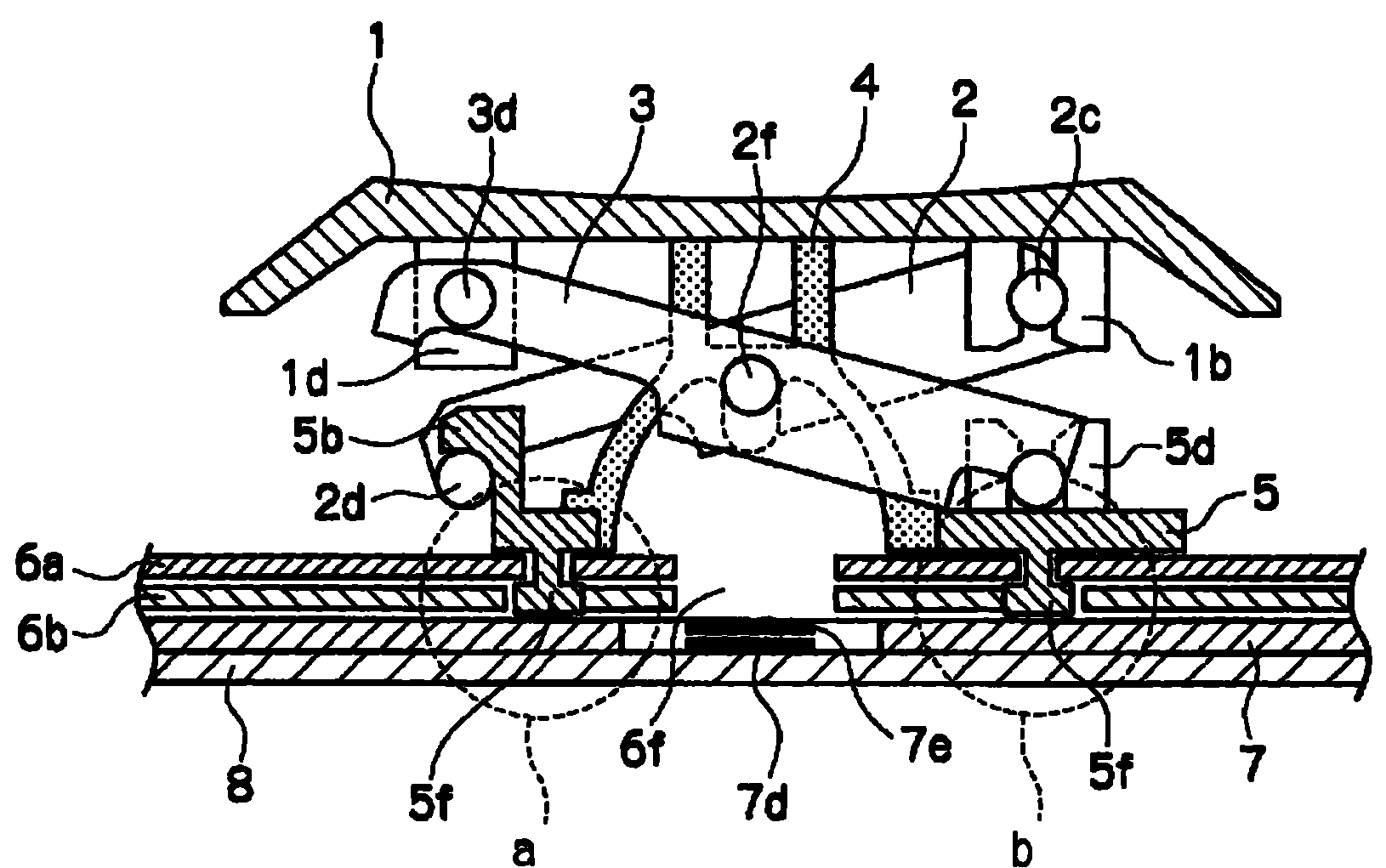
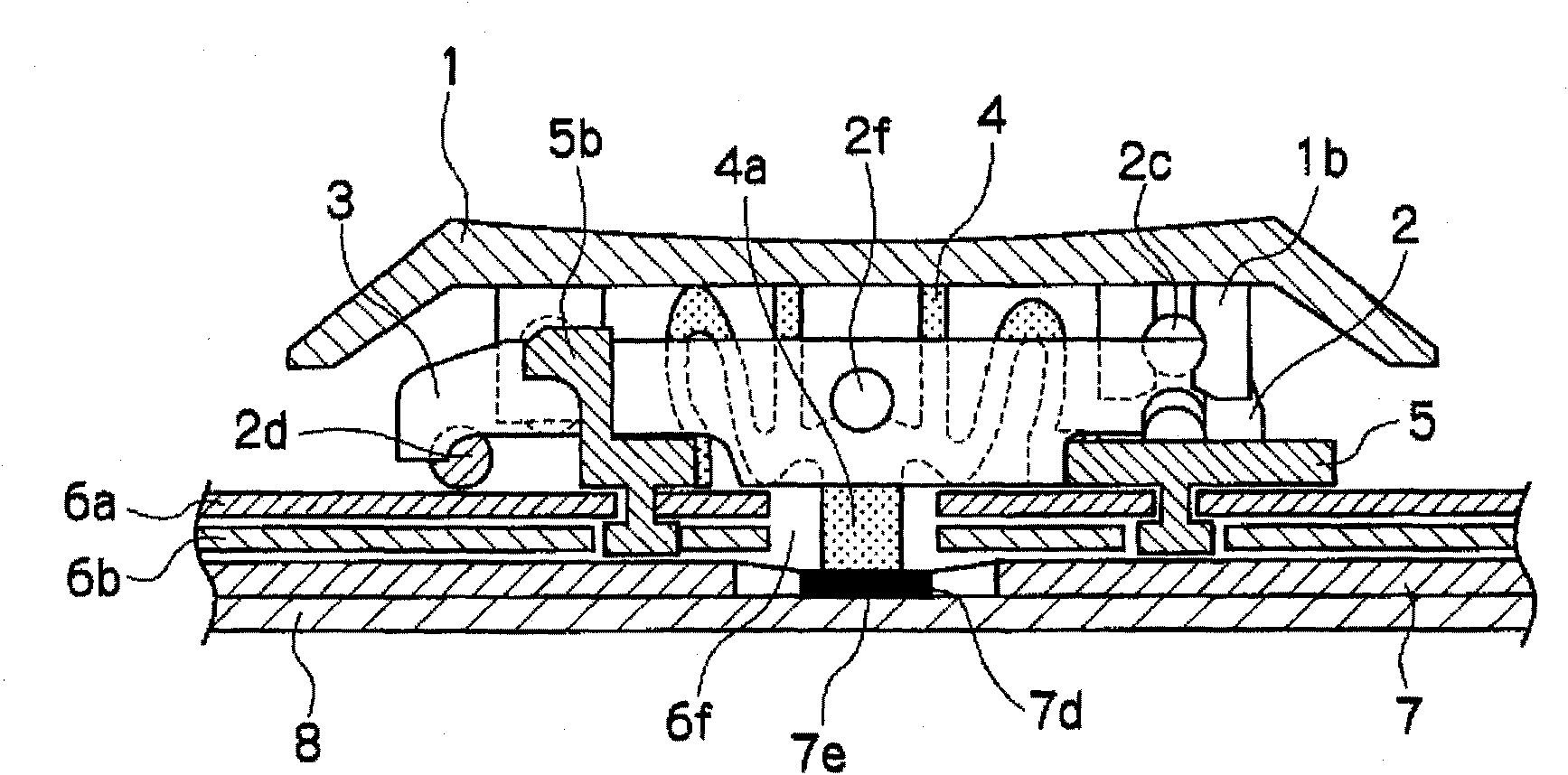
[0039] figure 1 It is a sectional view of the key switch of Embodiment 1, figure 2 It is an exploded perspective view of the key switch of the first embodiment.

[0040] The key switch is composed of the following components: a key top 1 , a first link part 2 , a second link part 3 , an elastic part 4 , a frame 5 , a plate 6 , a diaphragm 7 and a bottom plate 8 . The plate 6 is composed of an upper plate 6a and a lower plate 6b.

[0041] On the key top 1, rotation support portions 1a, 1b and slide support portions 1c, 1d are provided. The first link member 2 has a pair of leg portions 2a, 2b. A first connecting rod 2c is provided at one end of the legs 2a, 2b, and a second connecting rod 2d is provided at the other end of the legs 2a, 2b. In addition, rotation shafts 2e, 2f are provided on the leg portions 2a, 2b, respectively. The rotating shafts 2e, 2f are composed of two types of cylinders formed so that the diameter in the range from the middle...


PUM


Abstract

Provided is a key switch structure wherein a membrane sheet (7) having a movable contact point (7e) and a stationary contact point (7d) is provided between a housing (5), which supports a key top (1) so as to allow the key top to be pushed downward and a base plate (8). The movable contact point (7e) is brought into contact with the stationary contact point (7d) by a downward push to the key top (1), so that a switch is closed. In the key switch structure, the inside of a device's main body is completely shielded from outside air, and water is completely prevented from entering the inside of the device's main body. A plate (6) provided with a plurality of attachment holes (6g) corresponding to fixing pins (5f) of the housing (5) is provided on the membrane sheet (7), so that the fixing pins (5f) are secured in the attachment holes (6g) of the plate (6).

Description

technical field [0001] The present invention relates to a key switch structure in a keyboard device such as a personal computer. Background technique [0002] In recent mobile devices such as notebook personal computers (hereinafter referred to as "device bodies"), long-term portability is possible due to longer battery life, and all-weather devices are required. In order to realize this requirement, techniques for obtaining drip-proof properties and further water-repellent properties are required. For example, even when the keys are operated outdoors in rainy weather, there is a demand for a technology capable of preventing rainwater from entering the main body of the device from the keyboard. [0003] Figure 4 It is a cross-sectional view of a conventional key switch in consideration of this requirement, Figure 5 It is an exploded perspective view of a conventional key switch. [0004] As shown in this figure, the existing key switch structure consists of the followin...

Claims


Application Information

Patent Timeline
IPC IPC(8): H01H13/06H01H9/04H01H13/14H01H13/702
CPCH01H3/125H01H2223/002
Inventor 高木康
Owner JIANGSU TRANSIMAGE TECH CO LTD
Learn More