Winder

A technology of wire reels and wire reels, which is applied in the direction of electrical components, cable arrangement between relative moving parts, and cable installation, etc. It can solve the problems of uneven winding of wire reels and easy winding of wires, etc., and achieve uniform wiring , avoid winding problems and improve product performance

Inactive Publication Date: 2011-09-21
LG ELECTRONICS (TIANJIN) APPLIANCES CO LTD
View PDF7 Cites 3 Cited by
  • Summary
  • Abstract
  • Description
  • Claims
  • Application Information

AI Technical Summary

Problems solved by technology

[0009] However, the wire return device of the prior art wire reel has the following disadvantages. The wire reel drives the wire reel to rotate through the recovery of the built-in coil spring. Since the wire reel is always kept at the same position, the wire will Winds easily and does not wind evenly on the cord reel

Method used


Image

  • Winder
  • Winder
  • Winder

Examples


Embodiment Construction

[0030] The following is a further detailed description of the wire reel speed control device of the present invention in conjunction with the accompanying drawings and specific embodiments:

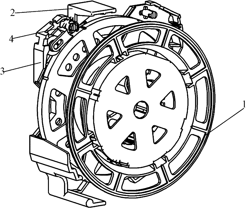
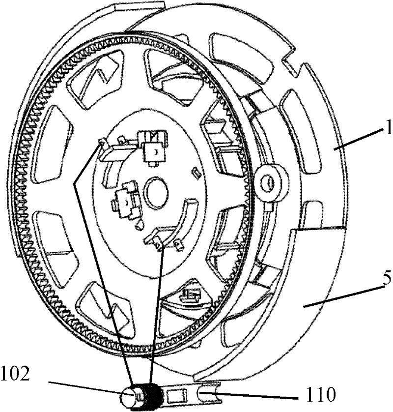
[0031] Such as Figure 2-5 Shown is the first embodiment of the present invention, a support 3 is provided on one side of the reel 1 of the cord reel in this embodiment, a coil spring box is provided on the other side, and a return button and a button are provided on the side of the support. The brake wheel also includes an electromagnetic speed limiting device, which is a magnet and a closed coil that can interact with each other when the reel 1 rotates.

[0032] The electromagnetic speed limiting device will first be described below in conjunction with the accompanying drawings:

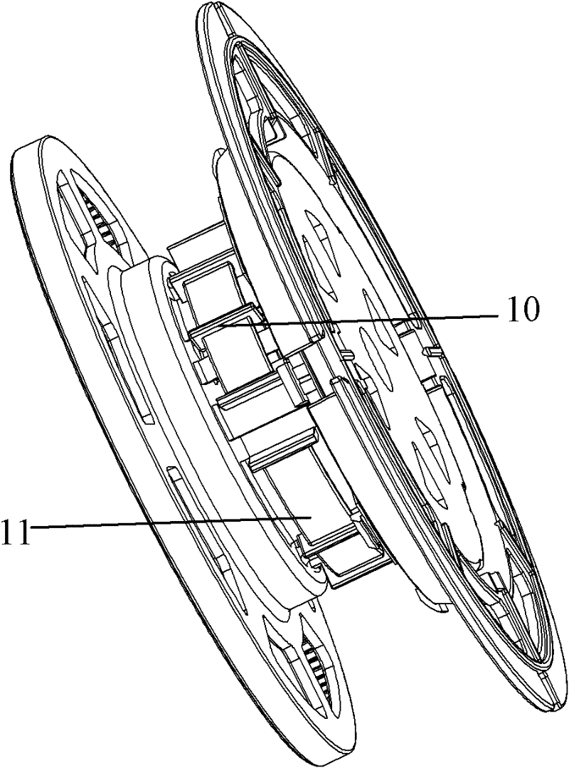
[0033] Such as figure 2 As shown, on the main shaft of the reel 1 of the line reel, a plurality of partitions 10 are protruding outward along its radial direction, and the partitions 10 are evenly distribut...


PUM


Abstract

The invention discloses a winder, comprising a winding wheel, a bracket capable of rotatively fixing the winding wheel; the side of the bracket is equipped with a loop button and a brake wheel; the line inlet of a cleaner is equipped with a power line limiting device; the limiting device can allow the power line to come in and go out, and the limiting device does reciprocating motion in the line inlet under the role of a drive device. The winder of the invention limits the position of the power line and compels the power line to generate right and left reciprocating motion relative to the winding wheel, changes the entry point of the power line on the winding part of the winding wheel, realizing uniform wiring, avoiding enwinding problem and improving the product performance.

Description

technical field [0001] The invention relates to a vacuum cleaner; in particular to a cord reel capable of uniform wiring. Background technique [0002] Generally, a vacuum cleaner is a device that uses a vacuum to generate suction to inhale air, make the air flow through various filters, filter foreign objects in the air, and clean the room. [0003] Generally speaking, a vacuum cleaner mainly includes a suction device and a suction pipeline. The suction device mainly formed by a motor and a fan is arranged in the body. The suction pipeline includes a suction head and a suction pipe. The suction head has a downward opening. The suction port communicates with the air inlet of the fan inside the body through the telescopic pipe and the flexible pipe of the suction pipe. When the vacuum cleaner is running, the motor drives the impeller of the fan to rotate at a high speed, exhausting the air in the vacuum cleaner, forming an instantaneous vacuum in the vacuum cleaner, and form...

Claims


Application Information

Patent Timeline
Patent Type & Authority Applications(China)
IPC IPC(8): A47L9/26
Inventor 任光智孟庆琛
Owner LG ELECTRONICS (TIANJIN) APPLIANCES CO LTD
Why Eureka
Try Eureka