Driver's cab electrical cabinet

A technology for electrical cabinets and driver's cabs, applied in the field of electrical cabinets, can solve the problems of maintainability, poor aesthetics, horizontal and vertical wiring harnesses, and low space utilization, so as to achieve clear and reasonable wiring harness arrangement, easy debugging and Reasonable effect of maintenance and equipment arrangement

Active Publication Date: 2017-02-22
CRRC NANJING PUZHEN CO LTD
View PDF1 Cites 0 Cited by
  • Summary
  • Abstract
  • Description
  • Claims
  • Application Information

AI Technical Summary

Problems solved by technology

The frame structure design scheme of the existing electrical cabinets on rail vehicles is relatively simple. For example, the Chinese patent with the publication date of 2014.3.5 and the application number of 201310602805.9 discloses "a D-shaped electrical cabinet". Although the design takes into account the installation stability , but the wiring is complicated and the maintenance is poor; there is also an electrical cabinet, such as Figure 1-2 Shown: There is no fixed main wiring harness area, resulting in intricate wiring in the cabinet, and the wiring harness cannot be horizontally flat and vertically
At the bend of the wire harness, the main wire harness is too thick, the stress is too large, and the aesthetics is poor
The wire harness that flows from the main wire harness to each equipment area is easy to be too thick, knotted, and squeezed
The arrangement of equipment and wiring in the entire cabinet is not coordinated, the space utilization rate is low, the maintainability and aesthetics are poor, the space in the cabinet is airtight, and the heat dissipation is poor

Method used


Image

  • Driver's cab electrical cabinet
  • Driver's cab electrical cabinet
  • Driver's cab electrical cabinet

Examples


Embodiment 1

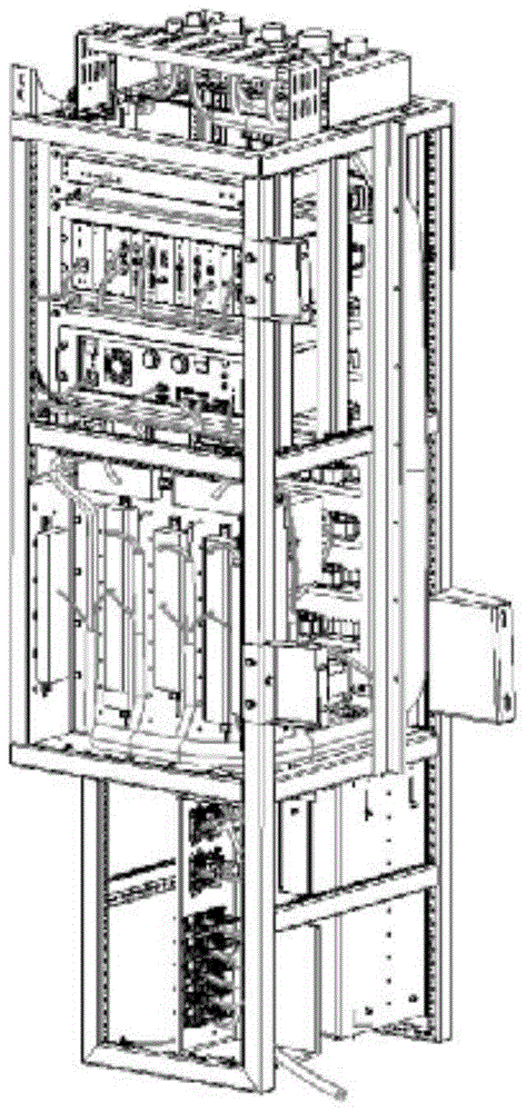
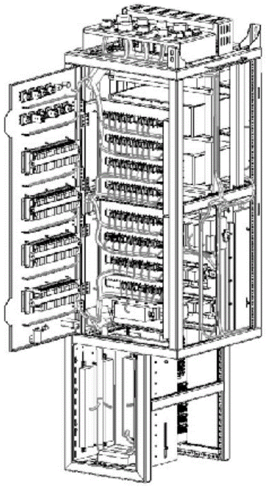
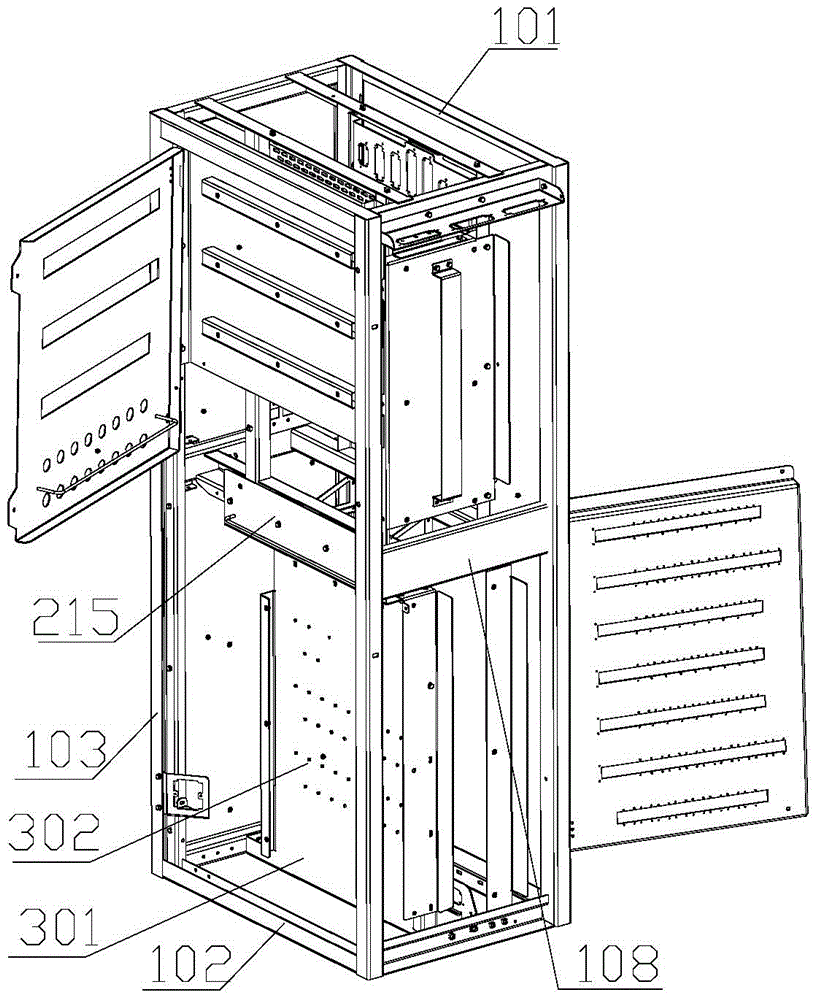
[0020] A kind of cab electric cabinet of this embodiment, such as Figure 3-7 As shown, it includes a rectangular parallelepiped outer frame composed of a rectangular top frame 101, a rectangular bottom frame 102, and four parallel columns 103. The four longitudinal sides of the outer frame are respectively a front frame 104, a back frame 105, and a first side frame 106. And the second side frame 107, the middle part of the first side frame 106 and the second side frame 107 is provided with the waist beam 108 perpendicular to the column, and the first side frame 106 is divided into the first upper side frame 109 and the first side frame 109 by the waist beam 108. The lower side frame 110, the second side frame 107 is divided into the second upper side frame 111 and the second lower side frame 112 by the waist beam 108, the front frame 104 has at least two first top rails 201 parallel to each other, two Between the waist crossbeams 108 are fixed two mutually parallel first inne...


PUM


Abstract

The invention relates to an electrical cabinet applicable to a cab. The electrical cabinet comprises a cuboid outer frame, and the cuboid outer frame is formed by combining a rectangular top frame, a rectangular bottom frame and a plurality of parallel stand columns. Waist beams perpendicular to the stand columns are arranged in the middles of two side frames of the outer frame respectively, and an internal secondary frame is fixed to the upper portion of the outer frame. An internal panel is fixed to the lower portion of the internal secondary frame, and a plurality of first wiring ducts perpendicular to the stand columns of the outer frame body are fixed to the internal panel. A plurality of second wiring ducts parallel with or perpendicular to the stand columns of the outer frame body are arranged in the side frames of the outer frame. The first wiring ducts are communicated with the second wiring ducts perpendicular to the stand columns of the outer frame body. Electrical products in the electrical cabinet are distributed evenly in order, the wiring directions are clear and orderly, and the electrical cabinet of the cab is convenient to maintain in the later stage due to the design.

Description

technical field [0001] The invention relates to an electrical cabinet, in particular to an electrical cabinet suitable for a driver's cab. Background technique [0002] There are a large number of electrical equipment and related cables carried by the electrical cabinet of the driver's cab on the rail vehicle. With the increase of electrical functions of rail vehicles. Equipment such as chassis equipment, disc-shaped equipment, a large number of low-voltage electrical components, and various electrical connection components need to be installed in the electrical cabinet of the driver's cab. The electrical cabinet in the driver's cab should not only play the role of a switchboard, but also serve as an installation carrier for large-scale equipment in various systems on the vehicle. The frame structure design scheme of the existing electrical cabinets on rail vehicles is relatively simple. For example, the Chinese patent with the publication date of 2014.3.5 and the applicat...

Claims


Application Information

Patent Timeline
Patent Type & Authority Patents(China)
IPC IPC(8): H02B1/01H02B1/26H02B1/20
Inventor 夏磊鲍伟兵于祥飞梁汝军
Owner CRRC NANJING PUZHEN CO LTD
Why Eureka
Try Eureka