A Low-Frequency Large-Displacement Angle Vibration Table

An angular vibration table and large displacement technology, which is applied in vibration testing, measuring devices, instruments, etc., can solve the problems of large output waveform distortion and small output angular displacement

Active Publication Date: 2016-09-14
ZHEJIANG UNIV
View PDF9 Cites 0 Cited by
  • Summary
  • Abstract
  • Description
  • Claims
  • Application Information

AI Technical Summary

Problems solved by technology

[0006] In order to overcome the disadvantage that the existing motor-driven angular vibrating table can output a large angular displacement, but the output waveform distortion is large; and the electromagnetic-driven angular vibrating table can output a small waveform distortion, but the disadvantage of small output angular displacement, the present invention An angular vibrating table with low output waveform distortion and large output angular displacement is provided

Method used


Image

  • A Low-Frequency Large-Displacement Angle Vibration Table
  • A Low-Frequency Large-Displacement Angle Vibration Table
  • A Low-Frequency Large-Displacement Angle Vibration Table

Examples


Embodiment 1

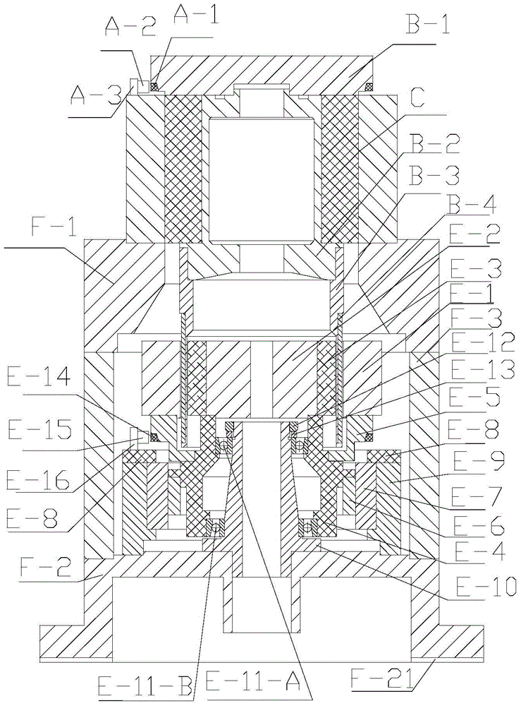
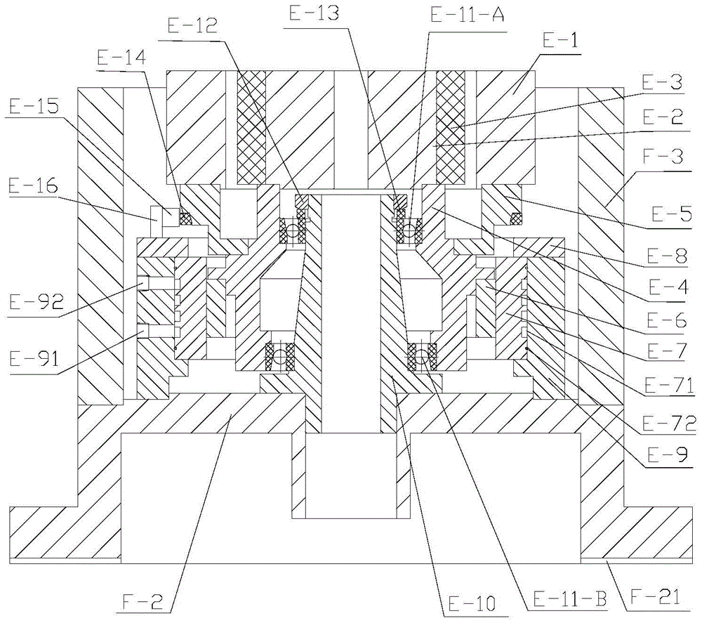
[0056] refer to Figure 1-6

[0057] Such as figure 1 As shown, a low-frequency large-displacement-angle vibrating table includes a housing, a worktable B-1, a spindle B-2 that drives the worktable B-1 to rotate, a moving coil assembly, a magnetic circuit assembly, a motor that drives the magnetic circuit assembly to rotate, and Its closed-loop control components, electro-viscoelastic feedback control components, air bearings and angular displacement sensors;

[0058] The main shaft B-2 is fixedly connected with the moving coil assembly, and the motor rotor E-6 is fixedly connected with the magnetic circuit assembly through the connecting piece;

[0059] The moving coil assembly includes a moving coil base B-3 connected to the main shaft B-2 and a coil B-4 wound on the moving coil base B-3, and the moving coil base B-3 is fixedly connected to the main shaft B-2;

[0060] The magnetic circuit assembly includes the magnetic ring E-1, the central magnetic pole E-2 and the magn...

Embodiment 2

[0079] The difference between this embodiment and the first embodiment lies in the specific structure of the air bearing, and the structure of other components except the air bearing is the same as that of the first embodiment.

[0080] Specifically: if Figure 7 As shown, the air bearing includes bearing seat C-1 and bearing body C-2, the main shaft B-2 is socketed in the bearing body C-2, the bearing body C-2 is socketed in the bearing seat C-1, and the bearing seat C -1 is fixed with the bearing body C-2, and the bottom of the main shaft B-2 is provided with a step matching with the bearing body C-2;

[0081] The outer surface of the bearing body C-2 is provided with a circular air intake groove C-21, and the bearing seat C-1 is provided with an air intake hole C-11 communicating with the air intake groove C-21, and the bearing body C -2 is provided with the radial air guide hole between the bearing body C-2 and the main shaft B-2, which guides the gas to the upper axial a...

Embodiment 3

[0092] refer to Figure 8 , 9 、10

[0093] The difference between this embodiment and Embodiment 1 lies in the coil of the moving coil assembly, and the structure of other components except the coil is the same as that of Embodiment 1.

[0094] Such as Figure 8 As shown, the coil B-4 of the moving coil assembly covers the outer surface of the moving coil base B-3. Such as Figure 9 As shown, the coil includes a coil winding B-4-1 and an insulating layer B-4-3, the coil winding B-4-1 and the insulating layer B-4-3 are arranged at intervals, and the coil winding B-4-1 has at least one layer , the insulating layer B-4-3 is made of epoxy resin glue and glass cloth, and the insulating layer completely covers the coil winding B-4-1 inside. Such as Figure 10As shown, the coil winding includes the first coil B-4-1-1 and the second coil B-4-1-2, the first coil B-4-1-1 is wound counterclockwise from inside to outside, the second coil B -4-1-2 Winding clockwise from outside to i...


PUM


Abstract

Low-frequency and large-displacement-angle vibrating table, including shell, worktable, main shaft that drives the worktable to rotate, moving coil assembly, magnetic circuit assembly, motor that drives the magnetic circuit assembly to rotate and its closed-loop control assembly, electroviscoelastic feedback control assembly, air bearing And angular displacement sensor; the main shaft is fixedly connected with the moving coil assembly, and the magnetic circuit assembly is fixedly connected with the motor rotor through the connector; the moving coil assembly includes the moving coil base and the coil, and the moving coil base is fixedly connected with the main shaft; the magnetic circuit assembly includes the magnetic ring , central magnetic pole and magnetic steel, a closed magnetic circuit is formed by the magnetic conducting ring, central magnetic pole, magnetic steel and air gap; Between them, the magnetic steel is adsorbed on the central magnetic pole; the moving coil assembly is located between the magnetic steel and the magnetic conducting ring, and the moving coil assembly is coaxial with the magnetic conducting ring. The invention has the advantages of low output waveform distortion and large output angular displacement.

Description

technical field [0001] The invention relates to a low-frequency large-displacement-angle vibrating table, in particular to an angular vibrating table used for calibration of an angular vibration sensor and capable of outputting low-frequency large-displacement vibrations. technical background [0002] The angular vibration table is not only widely used to calibrate the dynamic characteristics of various angular vibration (angular displacement, angular velocity, angular acceleration) sensors, but also to conduct angular vibration environmental tests on various products. [0003] At present, large-displacement-angle vibration tables with an angular displacement exceeding 180° generally adopt a structure based on a brushless motor. Jun Peng, Qun He, Jingfeng Xue and Hao Sun published a paper titled Low Frequency Standard Angle Shaker in the Journal of Measurement Technology, Volume 25, Issue 6, 2005. The low-frequency angular vibration table is mainly composed of a mechanical ...

Claims


Application Information

Patent Timeline
Patent Type & Authority Patents(China)
IPC IPC(8): G01D18/00G01M7/02
Inventor 何闻唐波贾叔仕周杰
Owner ZHEJIANG UNIV
Why Eureka
Try Eureka