Vacuum cleaner

A technology for vacuum cleaners and wire reels, which is applied in the direction of electrical components, cable arrangement between relative moving parts, and cable installation. The effect of looping and avoiding overlapping lines

Inactive Publication Date: 2011-12-07
LG ELECTRONICS (TIANJIN) APPLIANCES CO LTD
View PDF0 Cites 0 Cited by
  • Summary
  • Abstract
  • Description
  • Claims
  • Application Information

AI Technical Summary

Problems solved by technology

[0008] However, the wire return device of the vacuum cleaner cord reel in the prior art has the following disadvantages. The cord reel drives the cord reel to rotate through the restoring force of the built-in coil spring, and the winding of the power cord is random and uneven, which is easy to cause one-sided Arranging cables is also the main reason for not returning to the cable, not being able to pull out, etc.; it leads to greater complaints from customers and reduces the credibility of the company

Method used


Image

  • Vacuum cleaner
  • Vacuum cleaner
  • Vacuum cleaner

Examples


Embodiment Construction

[0027] The vacuum cleaner of the present invention will be further described in detail in conjunction with the accompanying drawings and specific embodiments:

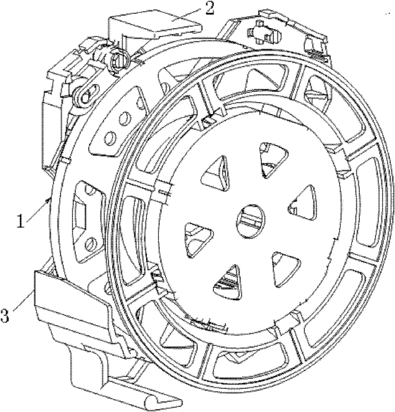
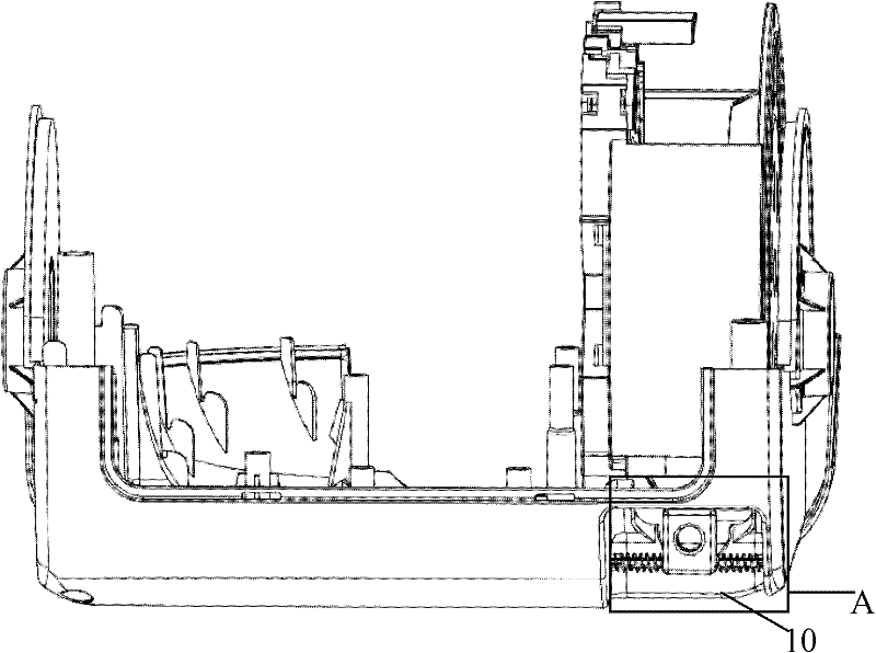
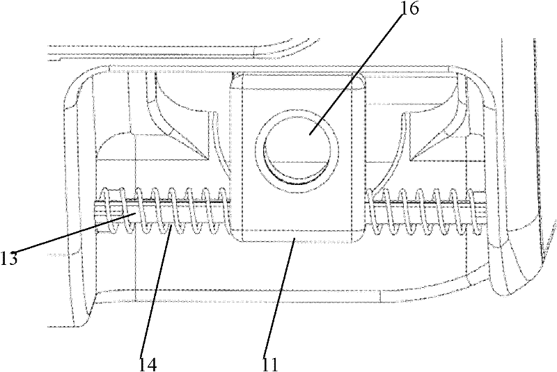
[0028] Such as Figure 2-3 Shown is the first embodiment of the present invention, a cavity 10 is recessed inwardly at the wire inlet of the vacuum cleaner, and a guide rod 13 is arranged in the cavity 10 parallel to the wire inlet , the two ends of the guide rod 13 are fixedly connected to the two side walls of the cavity 10, and the fixing method can be plugged in or the two ends of the guide rod 13 are fixed to the two ends of the guide rod 13 symmetrically formed on the two side walls of the cavity 10. Above the platform; the section of the guide rod 13 is a polygonal prism, preferably a square. A sliding block 11 is slidably sleeved on the guide rod 13, and the sliding block 11 can move left and right along the guide rod 13 relative to the wire inlet. The sliding block 11 is a rectangular structure, and its botto...


PUM


Abstract

The invention discloses a vacuum cleaner, which comprises a suction device, a suction pipeline and a wire reel, and an elastic disturbance device is arranged at the wire inlet of the vacuum cleaner wire reel, and the elastic disturbance device includes a A limiting device that swings left and right and a spring arranged between both sides of the limiting device and the body. The present invention arranges an elastic disturbance device at the wire inlet, increases the swing range of the power cord at the wire inlet to achieve uniform wiring, avoids the occurrence of overlapping wires caused by unilateral wiring of the power cord, and greatly reduces the non-returning and pulling The probability of occurrence of defects such as no wiring; and even if a flat power cord is used, there will be no overlapping of wires.

Description

technical field [0001] The invention relates to a vacuum cleaner; in particular, it relates to a uniform wiring device of the vacuum cleaner. Background technique [0002] Generally, a vacuum cleaner is a device that uses a vacuum to generate suction to inhale air, make the air flow through various filters, filter foreign objects in the air, and clean the room. [0003] Generally speaking, a vacuum cleaner mainly includes a suction device and a suction pipeline. The suction device mainly formed by a motor and a fan is arranged in the body. The suction pipeline includes a suction head and a suction pipe. The suction head has a downward opening. The suction port communicates with the air inlet of the fan inside the body through the telescopic pipe and the flexible pipe of the suction pipe. When the vacuum cleaner is running, the motor drives the impeller of the fan to rotate at a high speed, exhausting the air in the vacuum cleaner, forming an instantaneous vacuum in the vacu...

Claims


Application Information

Patent Timeline
Patent Type & Authority Applications(China)
IPC IPC(8): A47L9/26
Inventor 岳宏雷任光智
Owner LG ELECTRONICS (TIANJIN) APPLIANCES CO LTD
Why Eureka
Try Eureka