
Welding device used for copper craft production

A technology of copper handicrafts and welders, which is applied in the direction of welding equipment, welding equipment, auxiliary welding equipment, etc., and can solve problems such as welding defects

Inactive Publication Date: 2020-07-07
宁波鄞州区景行远望科技服务有限公司
View PDF0 Cites 6 Cited by
  • Summary
  • Abstract
  • Description
  • Claims
  • Application Information

AI Technical Summary

Problems solved by technology

[0004] Based on the technical problem that welding defects will be caused if the joints of the two spare parts are not matched enough when the sleeve fittings with the same inner diameter and different outer diameters are welded vertically, the invention proposes a welder for the production of copper handicrafts

Method used


Image

  • Welding device used for copper craft production
  • Welding device used for copper craft production
  • Welding device used for copper craft production

Examples


Embodiment 1

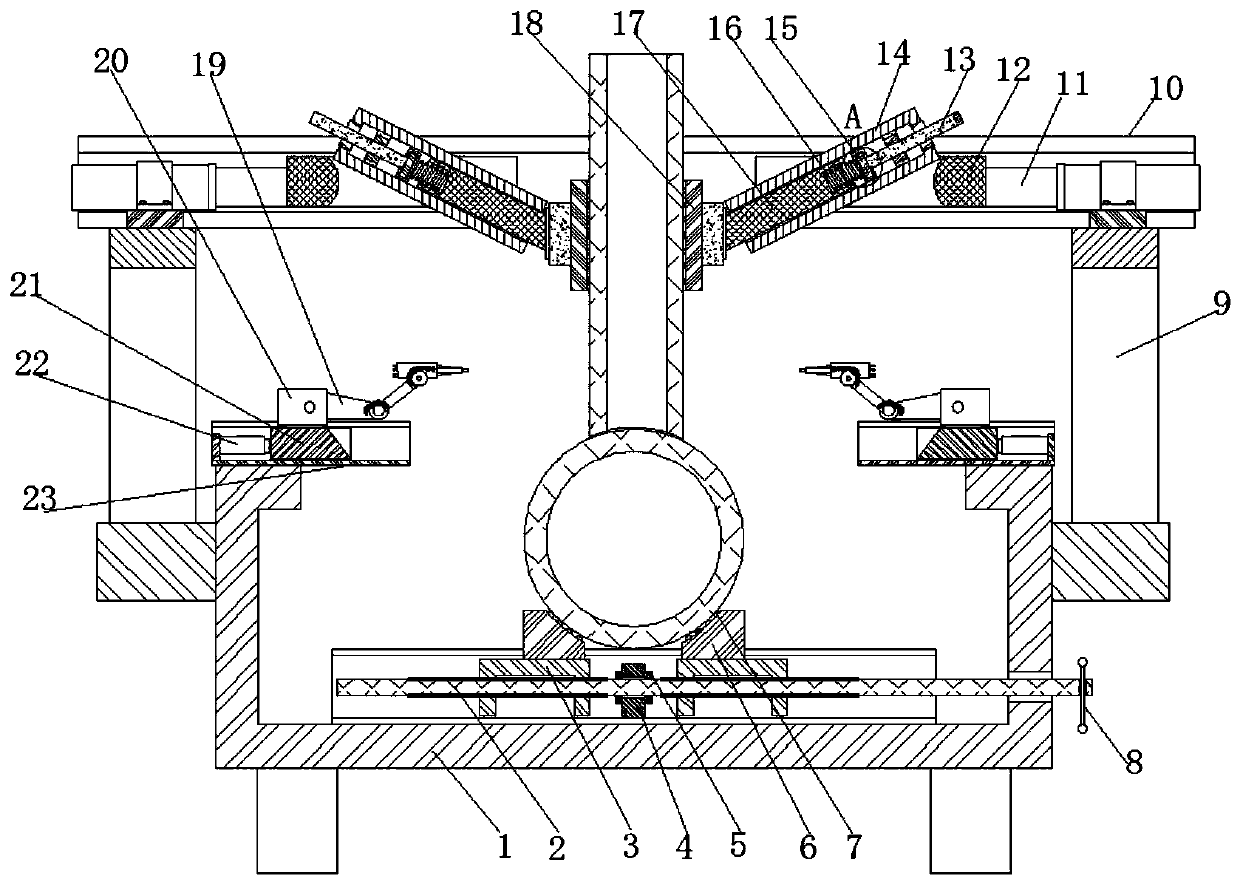
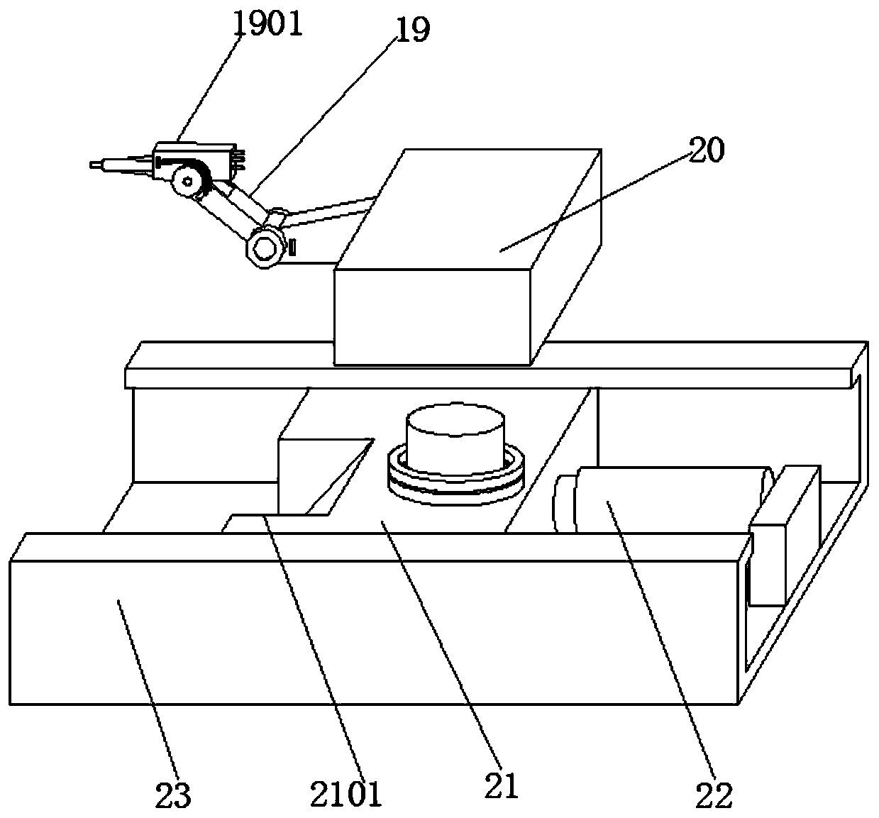
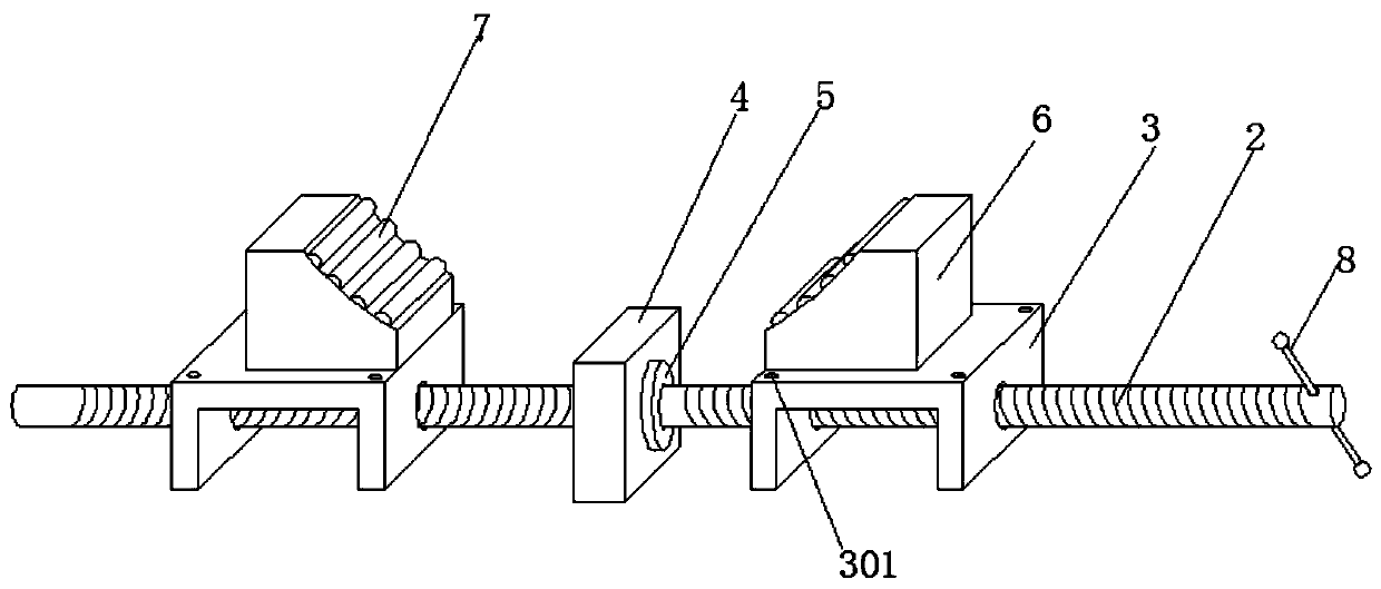
[0029] refer to Figure 1-5 , a welder for the production of copper handicrafts, including a base 1 with an upward opening in a groove-shaped structure, a C-shaped steel slide rail with an upward opening is fixed in the middle of the bottom of the base 1, and a stopper is fixed in the middle of the groove bottom of the C-shaped steel slide rail. Plate 4, the middle of baffle plate 4 is connected with two-way screw rod 2 for rotation, and the two ends of two-way screw rod 2 are sleeved with sliding blocks 3 respectively, and the tops of two sliding blocks 3 are respectively fixed with mutually symmetrical arc push plates 6, tube The seat is fixed between two arc-shaped push plates 6, and support frames 9 are fixed on opposite sides of the base 1, and two channel steel beams 10 with opposite openings and parallel to each other are fixed on the top of the two support frames 9. Two channel steel beams 10 are slidably connected with two C-shaped clamping blocks 12 with opposite ope...

Embodiment 2

[0039] refer to Figure 1-2 , a welder for the production of copper handicrafts. Compared with Embodiment 1, this embodiment also includes sockets that are equidistantly distributed on the side of the channel steel beam 10, and a C-shaped clamping block 12 is close to the socket. The side is embedded with an electric control positioning pin.

[0040] When the C-shaped clamping block 12 is moved into place during use, the electronically controlled positioning pin is activated to position it, preventing the C-shaped clamping block 12 from being forced to slide backwards and ensuring the stability of the device.


PUM


Abstract

The invention belongs to the technical field of copper craft production, and particularly relates to a welding device used for copper craft production. According to the solution adopted to solve the problem of welding defects caused by mismatching of the connected portions of two parts during vertical welding of sleeve parts with the same inner diameter and different outer diameters, the welding device comprises a base which is open upwards and is of groove-shaped structure, wherein a C-shaped steel sliding rail which is open upwards is fixed to the middle of the bottom of the base, a baffle is fixed to the middle of the groove bottom of the C-shaped steel sliding rail, a bidirectional screw rod is rotatably connected to the middle of the baffle, and the two ends of the bidirectional screwrod are sleeved with sliding blocks respectively. When the welding device used for copper craft production is used for welding a vertical weld tube, extension rods of hydraulic ejection rods can be controlled to extend to enable two arc clamping plates to move towards the middle to generate an oblique downward thrust, and at this moment, a downward force component is generated to tightly press the vertical weld tube on a tube holder, so that welds are minimized, and the welding quality is improved.

Description

technical field [0001] The invention relates to the technical field of copper handicraft production, in particular to a welder used for the production of copper handicrafts. Background technique [0002] During the production and processing of copper handicrafts, welding equipment is needed to weld the products. Due to the complex shape of the handicrafts, the difficulty of moving the handicrafts, and the wide distribution of solder joints, the welder needs to be moved during the welding process, and the existing welder is difficult. Move, increase the time and difficulty of welding process, improve the production cost of the whole copper handicraft. [0003] In the production process of existing copper handicrafts, it is often necessary to weld and fix different accessories together, especially when vertically welding sleeve accessories with the same inner diameter and different outer diameters, if the interface between the two parts is not consistent enough, it will be dam...

Claims


Application Information

Patent Timeline
IPC IPC(8): B23K37/053B23K31/02
CPCB23K31/02B23K37/053
Inventor 应近远
Owner 宁波鄞州区景行远望科技服务有限公司
Learn More