Self-lifting method for large scale steel structure supporting platform in limited space

A technology for supporting platforms and confined spaces, which is applied to the preparation of building components on site, pillars, building structures, etc., and can solve the problems of inability to meet the progress requirements and cost control of large-scale steel structure projects, construction safety cannot be guaranteed, and increase construction consumables Convenience and quickness of installation and disassembly, improvement of cycle life and reduction of construction cost

Active Publication Date: 2017-07-11
CHINA METALLURGICAL CONSTR ENG GRP
View PDF4 Cites 13 Cited by
  • Summary
  • Abstract
  • Description
  • Claims
  • Application Information

AI Technical Summary

Problems solved by technology

Due to the huge amount of installation and dismantling work of the large-scale support structure, the traditional installation and disassembly generally adopts welding and cutting methods. The steel members are easily damaged after repeated welding and cutting, and the construction safety cannot be guaranteed. At the same time, it increases Amount of construction consumables
This method is not only time-consuming, labor-intensive, low in efficiency, high in cost, but also ineffective. Obviously, it cannot meet the schedule requirements and cost control of large-scale steel structure projects. Moreover, some projects are limited by conditions and cannot use lifting equipment for mechanical lifting of the supporting platform. Operation

Method used


Image

  • Self-lifting method for large scale steel structure supporting platform in limited space
  • Self-lifting method for large scale steel structure supporting platform in limited space
  • Self-lifting method for large scale steel structure supporting platform in limited space

Examples


Embodiment Construction

[0038] The present invention will be described in further detail below in conjunction with specific embodiments.

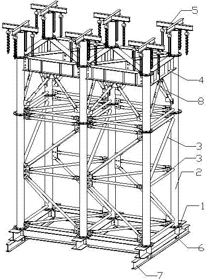
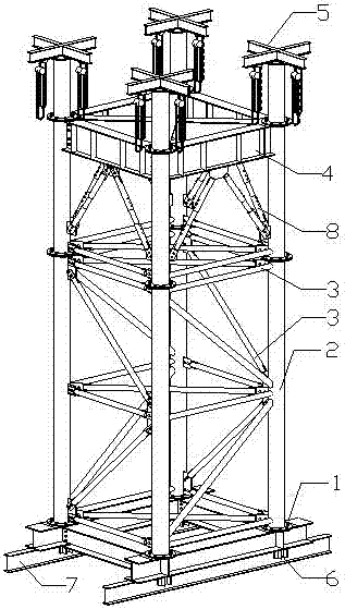
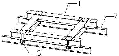
[0039] Such as Figure 1-6 As shown, a self-elevating method for a large-scale steel structure support platform in a confined space is characterized in that the method is based on a self-elevating steel structure support platform, which includes a sliding slide formed by two parallel-set I-beams or steel rails. Track 7, and several self-elevating steel structure sliding measure brackets arranged side by side on the sliding track 7; the self-elevating steel structure sliding measure support includes base 1, standard section, platform beam adjustment section and Lifting frame 5:

[0040] The base 1 includes two load-bearing beams arranged horizontally and parallel to each other, and two base connecting beams; the load-bearing beams are respectively placed on the upper end faces of the I-beams or rails; Fix the limit plate 6 to prevent the base from turning over th...


PUM


Abstract

The invention discloses a self-lifting method for a large scale steel structure supporting platform in a limited space, and the method bases on a self-lifting steel structure supporting platform. The self-lifting steel structure supporting platform comprises a sliding orbit composed of two joist steels or steel rail which are arranged in parallel and a plurality of self-lifting steel structure sliding measure supports arranged on the sliding orbit side by side; each self-lifting steel structure sliding measure support comprises a base, standard mast sections, a platform beam adjusting section and a lifting frame. Operation steps comprise that quantity of needed self-lifting steel structure sliding measure supports is measured, then the sliding orbit and the base are installed, and N of the standard mast sections, the platform beam adjusting section and the lifting frame are installed on each base in sequence. According to the requirement for construction height, a rectangular ring beam is lifted to a pointed elevation position by one of the top lifting frame and is fixed. According to the self-lifting steel structure supporting platform and the self-lifting method, lifting work of a large scale supporting structure can be conducted by fully relying on manpower, mounting and dismounting are convenient, efficiency is high, needed materials are less, cost is low, and cycle use can be achieved.

Description

technical field [0001] The invention belongs to the technical field of steel structure construction, and in particular relates to a self-elevating method for a large-scale steel structure support platform in a limited space. Background technique [0002] At present, the height of steel structure engineering is getting higher and higher, and the span is getting bigger and bigger, resulting in the measures used in the installation process to support the structure is also getting bigger and higher, especially in the installation process using slip and lifting When the more advanced installation technology is used, the requirements for the supporting structure of the measures are higher. When the roof of some large-scale steel structure projects is constructed by the high-altitude sliding method, since the sliding unit needs to be closed at high altitude, measures need to be erected to support the platform. Due to the huge amount of installation and dismantling work of the larg...

Claims


Application Information

Patent Timeline
Patent Type & Authority Applications(China)
IPC IPC(8): E04G25/00E04G25/06
CPCE04G25/00E04G25/06E04G2025/003
Inventor 刘金芳徐国友周敬
Owner CHINA METALLURGICAL CONSTR ENG GRP
Why Eureka
Try Eureka