Linear switch magnetic flux permanent magnet motor with low location force and high thrust

A permanent magnet motor, switching magnetic flux technology, applied in the direction of electric components, electrical components, electromechanical devices, etc., can solve the problems of unfavorable promotion and application of linear motors, large thrust fluctuations, and a large number of permanent magnets, and achieves favorable heat dissipation and efficiency. Cooling, improving output and service life, reducing the effect of magnetic field harmonics

Inactive Publication Date: 2012-12-19
JIANGSU ZHONGRONG ELECTRIC +1
View PDF5 Cites 0 Cited by
  • Summary
  • Abstract
  • Description
  • Claims
  • Application Information

AI Technical Summary

Problems solved by technology

However, the number of permanent magnets placed on the long secondary stator is large, and the cost is high, which is not conducive to the popularization and application of linear motors. Therefore, manufacturing cheap switched reluctance linear motors has become one of the choices in this field.
The defect of the switched reluctance linear motor is also obvious. The thrust fluctuates greatly during operation, and the mechanical noise has always been a problem that is difficult to solve.

Method used


Image

  • Linear switch magnetic flux permanent magnet motor with low location force and high thrust
  • Linear switch magnetic flux permanent magnet motor with low location force and high thrust

Examples


Embodiment Construction

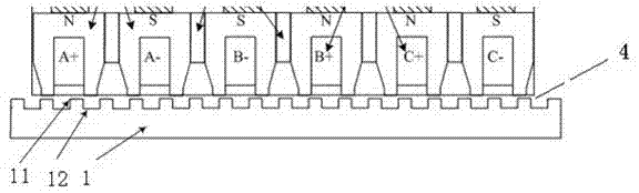
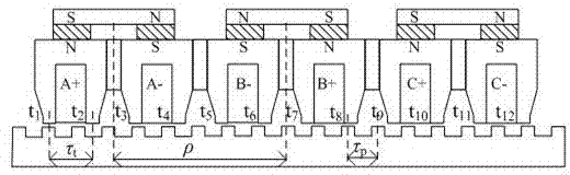
[0021] A novel linear plate type switched flux permanent magnet motor according to the present invention, comprising a primary iron core 21, a permanent magnet 22, a magnetically conductive bridge 24, a non-magnetically conductive spacer 23, a three-phase winding 3, a secondary mover 1 and a gas gap 4, such as figure 1 . The whole motor has a flat plate structure, and two permanent magnets with opposite magnetization directions are placed between two U-shaped iron cores in the same phase and the two ends of the magnetic permeable bridge to form a closed magnetic circuit. The primary three-phase winding is embedded in the U-shaped slot of the primary iron core in the form of single-layer concentrated winding, and the air gap is located between the primary and secondary of the motor. The primary iron core can be made of silicon steel sheets, and the secondary stator air gap side is a U-shaped pole and slot structure with the same interval, which can be processed from a whole p...


PUM


Abstract

The invention discloses a linear plate type switch magnetic flux permanent magnet motor. The motor comprises a secondary stator and a primary rotor. The primary rotor comprises U-shaped iron cores with U-shaped sections, permanent magnets, a non-magnetic conductor interval, a magnetic conduction bridge and a primary three-phase winding. The non-magnetic conductor interval is arranged between the two adjacent U-shaped iron cores. The non-magnetic conductor interval and the U-shaped iron cores are same in thickness. The magnetic conduction bridge is arranged on the tops of the U-shaped iron cores. Two permanent magnets which are same in thickness and opposite in magnetization direction are installed between the two U-shaped iron cores of same phase and the magnetic conduction bridge. The secondary stator is provided with an electrode and a groove on the surface which is just opposite to the primary rotor. The electrode and the groove can be precisely located and controlled by a controller driven by sine-wave current. A gas clearance is arranged between the U-shaped iron core of the primary rotor and the secondary rotor. The motor disclosed by the invention is used in a direct drive type alternating-current transmission system; and an intermediate transmission structure and a speed changing device are unnecessary. The motor can be used as a direct drive motor of a feeding drivingsystem of a numerical control machine. The motor can also be applicable to a translation transmission system with a locating function.

Description

technical field [0001] The invention is used in the fields of translational transmission or machine tool feed drive with positioning requirements, and relates to a new type of linear flat switch flux permanent magnet motor, specifically a low positioning force high thrust linear switch flux permanent magnet electric motor. Background technique [0002] At present, high-end CNC machine tools using linear motors as feed drive motors are becoming more and more technical hotspots in the industry. This is because the traditional "rotary servo motor + ball screw" feed method is limited in improving various performances, while the linear The motor has great potential in improving various performances. However, due to the existence of the edge effect of the linear motor, the uneven magnetic field during operation causes the disadvantage of large thrust fluctuations. Moreover, since the linear motor is directly connected to the processing tool, the disturbance and friction of the ...

Claims


Application Information

Patent Timeline
Patent Type & Authority Patents(China)
IPC IPC(8): H02K41/03
Inventor 孙国平余海涛冯四平周士贵朱斌
Owner JIANGSU ZHONGRONG ELECTRIC
Why Eureka
Try Eureka