Current-mode-logic-based high speed high-oscillation amplitude divide-by-two frequency divider circuit

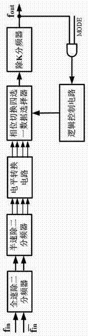
A current-mode logic, two-frequency divider technology, applied in the direction of electrical components, automatic power control, etc., can solve the problems of multi-chip area, extra power consumption, etc., to achieve a wide frequency input range, reduce complexity, high resistance Effects of Interference Ability

Inactive Publication Date: 2013-01-23
EAST CHINA NORMAL UNIV
View PDF3 Cites 3 Cited by
  • Summary
  • Abstract
  • Description
  • Claims
  • Application Information

AI Technical Summary

Problems solved by technology

In the end, this will make the entire dual-mode frequency divider generate some additional power consumption and occupy more chip area

Method used


Image

  • Current-mode-logic-based high speed high-oscillation amplitude divide-by-two frequency divider circuit
  • Current-mode-logic-based high speed high-oscillation amplitude divide-by-two frequency divider circuit
  • Current-mode-logic-based high speed high-oscillation amplitude divide-by-two frequency divider circuit

Examples


Embodiment

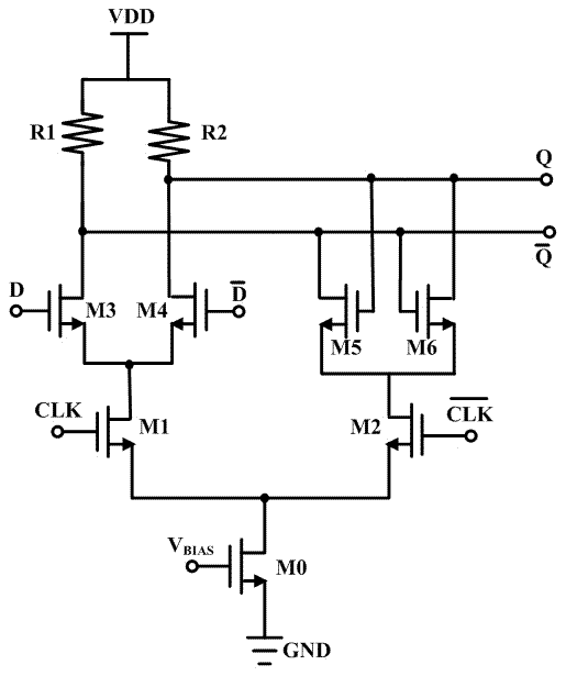
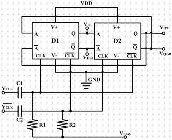
[0021] This embodiment has the accompanying image 3 , 4 The circuit shown has exactly the same circuit structure, and the components and circuit parameters of this embodiment are listed as follows:

[0022] The capacitances of the first capacitor C1 and the second capacitor C2 are respectively: 2.45544pF and 2.45544pF.

[0023] The resistances of the first resistor R1 and the second resistor R2 are respectively: 1.13398 KΩ and 1.13398 KΩ.

[0024] The first MOS transistor M1, the second MOS transistor M2, the third MOS transistor M3, the fourth MOS transistor M4, the fifth MOS transistor M5, the sixth MOS transistor M6, the seventh MOS transistor M7, the eighth MOS transistor M8, the ninth MOS transistor The width-to-length ratio dimensions (W / L) of the MOS tube M9, the tenth MOS tube M10, and the eleventh MOS tube M11 are: 140um / 0.2um, 140um / 0.2um, 9um / 0.18um, 9um / 0.18um, 8.2 um / 0.18um, 8.2um / 0.18um, 9um / 0.18um, 9um / 0.18um, 18um / 0.18um, 18um / 0.18um, 280um / 0.2um.

[0025]...


PUM


Abstract

The invention discloses a high speed high-oscillation amplitude divide-by-two frequency divider circuit, which belongs to the technical fields of integrated circuit designing and signal processing. Specifically, the circuit mainly comprises two high speed high-oscillation amplitude D triggers which are cascaded. The D trigger of each stage eliminates the bias of a tail current source based on theconventional D trigger having a current-mode logic (CML) structure, and adopts a P-channel metal oxide semiconductor (PMOS) transistor as a load; and simultaneously, a PMOS and N-channel metal oxide semiconductor (NMOS) complementary cross coupling pair structure and the like are adopted by the output stage of the circuit to finally achieve the aims of increasing the oscillation amplitude of an output signal and making the oscillation amplitude of the output signal approximate to full oscillation amplitude under the condition of ensuring the high speed working of the circuit. The circuit not only can directly drive a post circuit, reduces system power consumption to a certain extent, compensates for the shortcomings of a conventional divide-by-two frequency divider, and is suitable for a high speed frequency divider part in a low-power consumption preposed dual-mode prescaler front-end without any additional level conversion amplification circuit.

Description

technical field [0001] The invention belongs to the technical field of integrated circuit design and signal processing, and specifically relates to a high-speed large-swing divide-by-two frequency divider circuit operating at 2.5GHz-5.5GHz based on current mode logic, which is mainly used in ultra-high frequency wireless communication systems in the frequency synthesizer. Background technique [0002] In recent years, driven by the rapid development of the integrated circuit industry, wireless communication technology is undergoing rapid changes. Wireless communication technology is widely used in mobile phones, wireless local area network (WLAN), ultra-high frequency radio frequency identification (UHF RFID), global positioning system (GPS), etc., and various standard protocols and technical applications emerge in endlessly. The wireless communication system is also developing in the direction of faster and faster transmission rate, higher and higher security performance, ...

Claims


Application Information

Patent Timeline
Patent Type & Authority Patents(China)
IPC IPC(8): H03L7/18
Inventor 李征张润曦谢淼黄龙赖宗声
Owner EAST CHINA NORMAL UNIV
Why Eureka
Try Eureka