

Functional shoe
A functional, in-shoe technology, applied in footwear, apparel, applications, etc., to solve problems such as difficulty in fitting arches of different sizes
- Summary
- Abstract
- Description
- Claims
- Application Information
AI Technical Summary
Problems solved by technology
Method used
Image

Examples
no. 1 example
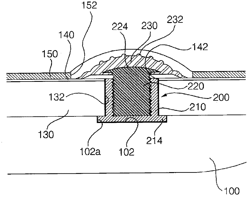
[0031] figure 1 is a diagram showing a state to which the arch support of the functional shoe according to the first embodiment of the present invention is applied.
[0032] As shown in the figure, an outsole 100 is placed on the bottom, and a midsole 130 , an insole board 140 , and an insole 150 are stacked on the outsole 100 .
[0033] According to the present invention, the receiving grooves 142, 132, 102 are formed to connect and pass through the insole plate 140 corresponding to the arch of the wearer's foot, the midsole 130 and the outsole 100, and the arch support 200 is accommodated by these. The slots 142, 132, 102 clamp sequentially.
[0034] In the uppermost insole 150 , an opening 152 is formed at a portion corresponding to the arch support 200 , whereby the contact part 230 of the arch support 200 is exposed. On the contrary, no opening may be formed, resulting in a good appearance. At this time, the thickness of the part of the insole 150 corresponding to the ...
no. 2 example
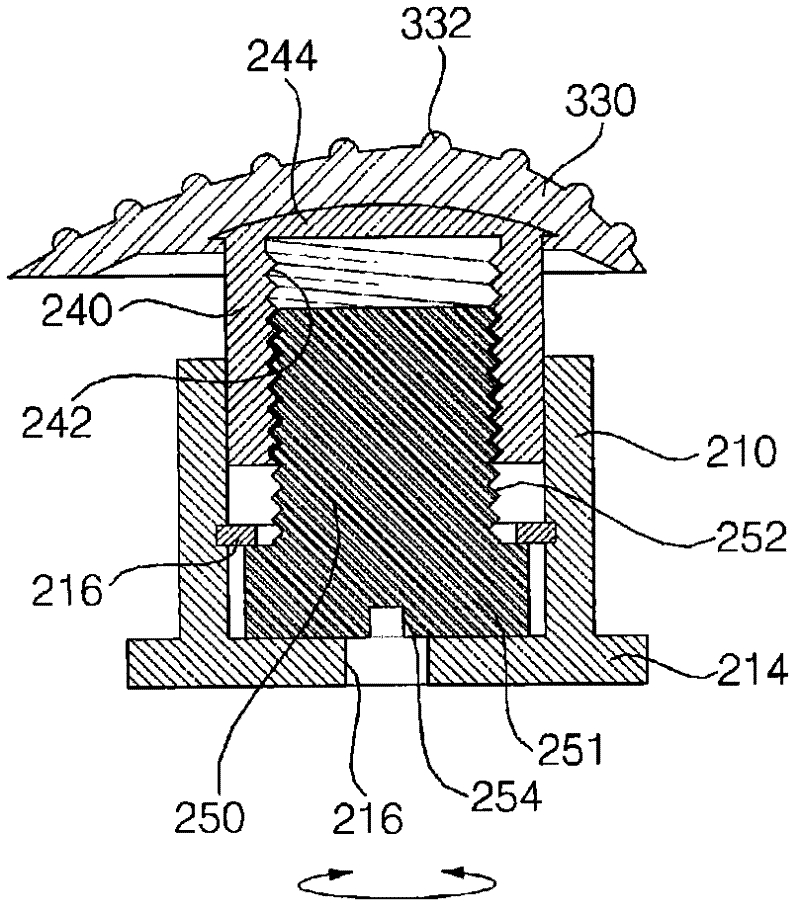
[0047] image 3 is a sectional view showing an arch support according to a second embodiment of the present invention.
[0048] This embodiment is applicable to a case where it is difficult to adjust the height by rotating the contact part 330 itself.
[0049] refer to image 3 , having a shape similar to the arch of the actual foot (cf. Figure 4 ) The inside of the contact member 330 is combined with a slider 240. The slider 240 has a cylindrical shape with a thread 242 formed on its inner side wall, and the slider 240 is fixed by combining the upper head 244 with the contact member 330 .
[0050] The inside of the slider 240 is clamped with a screw 250 for screw connection, and a groove 254 is formed on the head 251 of the screw 250. When the screw 250 is rotated by using the groove 254, the thread 252 of the screw 250 and the thread 242 of the slider 240 Screwing is performed so that the slider 240 is raised and lowered.
[0051] The center of the bottom surface of th...
no. 3 example
[0056] Figure 4 are perspective and sectional views showing an arch support according to a third embodiment of the present invention.
[0057] Like the second embodiment, this embodiment is applicable to a case where it is difficult to adjust the height by rotating the contact member 330 itself.
[0058] refer to Figure 4 A pair of support rods 333, 334 are formed on the inside of the contact part 330 having a shape similar to the arch of an actual foot. The distance between the pair of support rods 333 , 334 may be greater than the diameter of the housing 210 .
[0059] According to this embodiment, the guide grooves 134 , 135 in which the support bars 333 , 334 are sandwiched are formed on the midsole 130 .
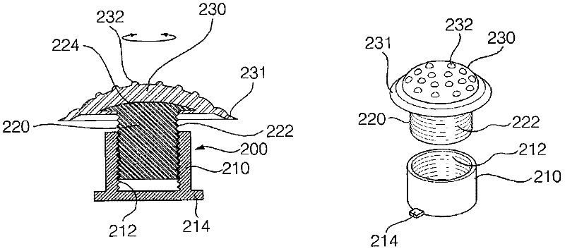
[0060] In addition, like the first embodiment, the slider 220 has a cylindrical shape, and the upper portion of the slider 220 is integrally formed with a substantially hemispherical head 224 to be detachably combined with the contact member 330 .
[0061] The ope...
PUM
 Abstract
Description
Claims
Application Information