Double-capacity power transformer

A power transformer and capacity technology, applied in the field of transformers, can solve problems such as power grid outage, transformer outage, loss, etc., and achieve the effects of controlling magnetic flux leakage path, reducing temperature rise, and improving service life

Active Publication Date: 2012-03-07
SHANDONG POWER EQUIP
View PDF6 Cites 11 Cited by
  • Summary
  • Abstract
  • Description
  • Claims
  • Application Information

AI Technical Summary

Problems solved by technology

[0002] During the operation of the power grid, sometimes the transformer fails and stops due to external environmental damage or the transformer itself, and other transformers cannot bear the load of the faulty transformer, causing the entire power grid to stop immediately and cause serious losses.

Method used


Image

  • Double-capacity power transformer
  • Double-capacity power transformer
  • Double-capacity power transformer

Examples


Embodiment 1

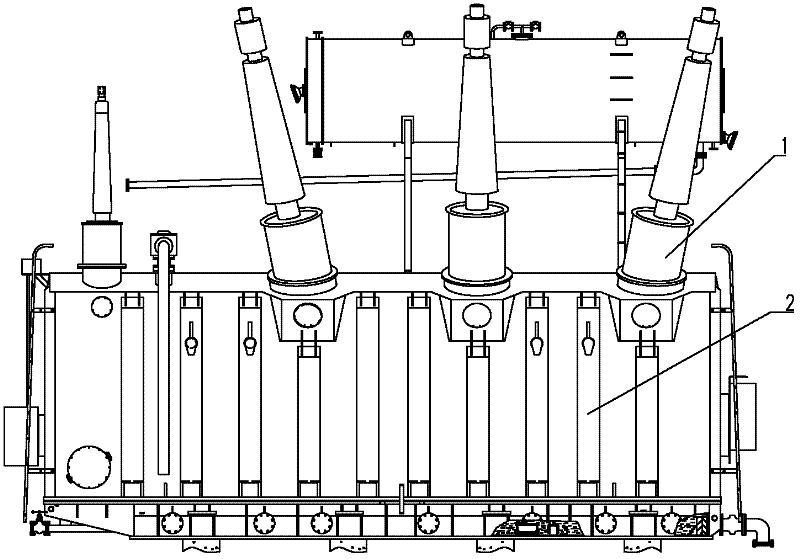
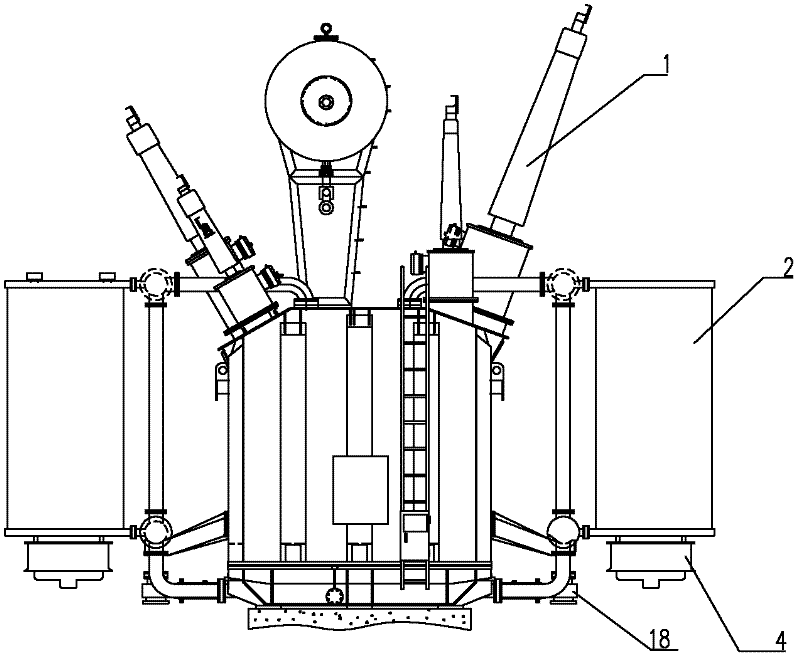
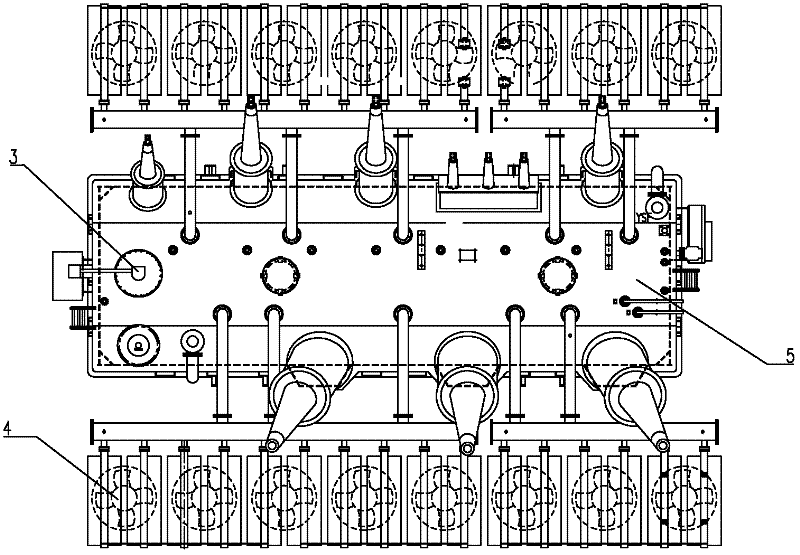
[0020] A double-capacity power transformer, as shown in the figure, includes an oil tank 5, an iron core 7, a winding, a fin radiator 2 and a cooling device installed outside the oil tank, each winding end is provided with a clamp 8, the inner wall of the oil tank 5 and the clamp Magnetic shields 6, 9 are provided on the piece 8, and the thickness of the magnetic shields 6, 9 is 10 mm. The windings include a low-voltage winding 14, a medium-voltage winding 12, a high-voltage winding 11, and a voltage-regulating winding 17 on one side of the high-voltage winding, which are sequentially set on the iron core 7. The high-voltage winding 11 and the medium-voltage winding 12 adopt an inner screen continuous structure The low-voltage winding 14 adopts a continuous structure, the voltage-regulating winding 17 adopts a double-helix structure, the high-voltage winding 11 adopts semi-hard copper transposed wires, and the medium-voltage winding 12 and low-voltage winding 14 adopt semi-hard...

Embodiment 2

[0022] In this embodiment, the thickness of the magnetic shield is 25mm, and the winding current density is 2.2A / mm 2 , the width of the wire at the end of the winding is 8.5mm, the width of the high-voltage winding oil passage spacer is 45mm, the width of the axial oil passage is 6mm, and the width of the winding oil passage is 6mm.

Embodiment 3

[0024] In this embodiment, the thickness of the magnetic shield is 20mm, and the winding current density is 2A / mm 2 , the width of the wire at the end of the winding is 7.5mm, the width of the high-voltage winding oil passage spacer is 40mm, the axial oil passage width is 6mm, and the winding oil passage width is 5mm. Other features are the same as those in Embodiment 1 and will not be repeated here.


PUM

PropertyMeasurementUnit
widthaaaaaaaaaa
widthaaaaaaaaaa
widthaaaaaaaaaa

Abstract

The invention relates to the technical field of transformers, particularly to a double-capacity transformer having a load capacity for short-time emergency treatment. Magnetic shields are arranged on the inner wall of an oil tank and a clamp of the transformer; a high-voltage winding and a medium-voltage winding of the transformer are both of an internal shield continuous structure; a low-voltagewinding is of a continuous structure; a tap-changing winding is of a double-helix type structure; a half-hard copper transposed conductor is adopted for the high-voltage winding; half-hard copper self-adhesive transposed conductors are adopted for the medium-voltage winding and the low-voltage winding; the current density of each winding is 1.7-2.2 A / mm<2>; the width of a conductor on the end part of each winding is 6-8.5 mm; the thickness of the magnetic shield is 10-25 mm; at least one axial oil passage is radially arranged in the high-voltage winding and the medium-voltage winding; and secondary struts are also arranged in the windings at the internal side. By using the double-capacity power transformer disclosed by the invention, the loss and the temperature rise of the transformer are reduced, the service life of the transformer is prolonged, the transformer has the 200%load capacity for the short-time emergency treatment, the flexibility of power grid dispatching is improved, and the safe operation of a power grid is guaranteed.

Description

technical field [0001] The invention relates to the technical field of transformers, in particular to a double-capacity transformer with short-term emergency load capacity. Background technique [0002] During the operation of the power grid, sometimes the transformer fails due to external environmental damage or the transformer itself, and other transformers cannot bear the load of the faulty transformer, resulting in the immediate shutdown of the entire power grid, resulting in serious losses. If each transformer in the power grid can be made to have a greater overload capacity, then when one transformer is out of operation due to a fault, the other transformer can bear all the load of the faulty transformer in a short time, and the power grid can be maintained for a period of time. It can greatly improve the flexibility of power grid dispatching and reduce the failure loss of power grid operation transformers. Contents of the invention [0003] In view of the above pro...

Claims


Application Information

Patent Timeline
Patent Type & Authority Applications(China)
IPC IPC(8): H01F27/30H01F27/28H01F27/29H01F27/36H01F27/12
Inventor 赵永志唐秋茹刘克民惠增明柴孟东徐富强韦良斌
Owner SHANDONG POWER EQUIP
Why Eureka
Try Eureka