Braking Device

A brake device and brake fluid technology, which is applied in the direction of brake transmission, brakes, transportation and packaging, etc., can solve the problems of insufficient brake fluid volume and insufficient responsiveness, etc.

Inactive Publication Date: 2012-03-14
ADVICS CO LTD
View PDF5 Cites 11 Cited by
  • Summary
  • Abstract
  • Description
  • Claims
  • Application Information

AI Technical Summary

Problems solved by technology

[0005] However, when the electronic system (such as the brake ECU) fails, the output piston has to be directly pressed to generate the braking force, so the above-mentioned gap between the input piston and the output piston becomes an invalid stroke.
Therefore, the responsiveness at the time of brake operation is insufficient, and the amount of brake fluid output from the M / C to the wheel cylinder (hereinafter referred to as W / C) may become insufficient due to the difference in the size of the gap.

Method used


Image

  • Braking Device
  • Braking Device
  • Braking Device

Examples


no. 1 approach

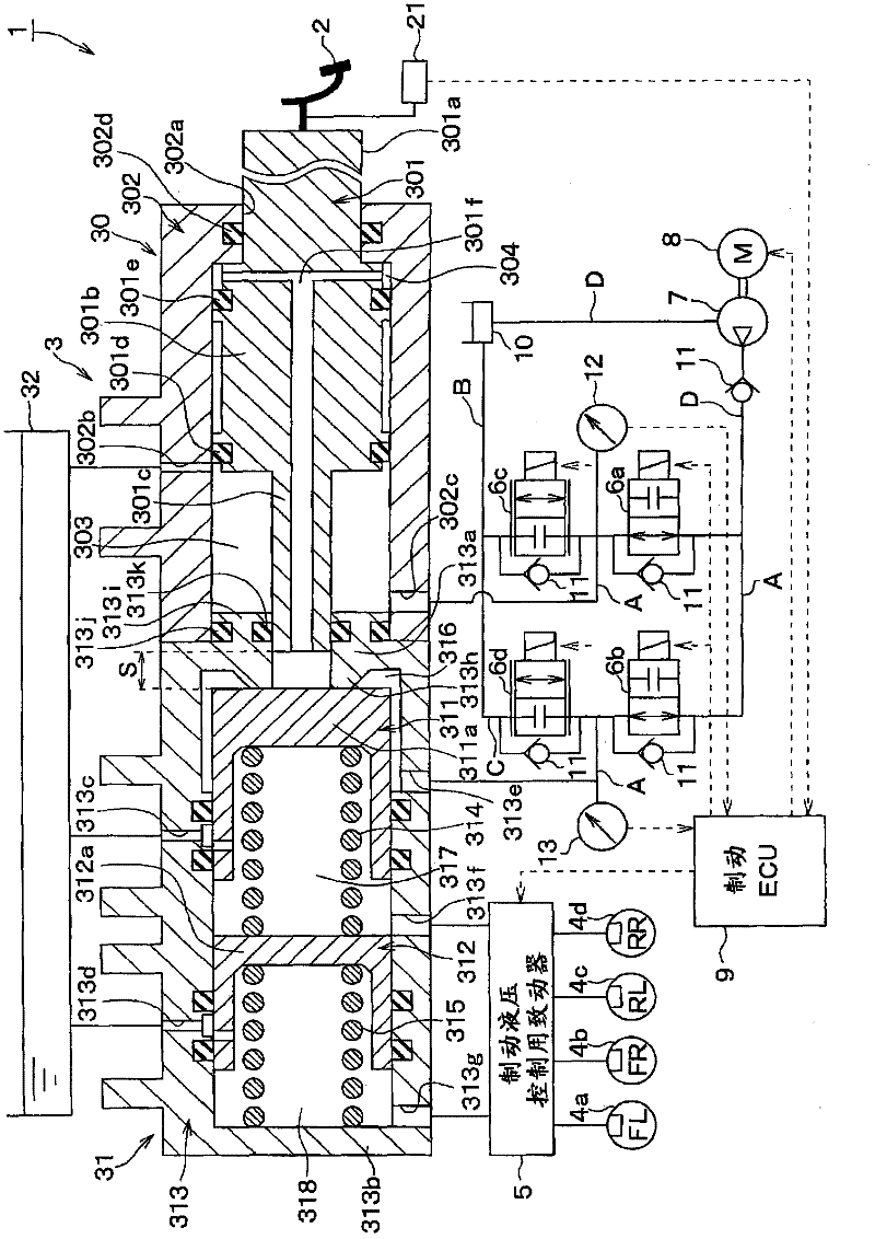
[0030] A first embodiment of the present invention will be described. figure 1 The overall configuration of the vehicle brake device 1 to which the first embodiment of the present invention is applied is shown. Below, refer to figure 1 , the brake device 1 of the present embodiment will be described.

[0031] Such as figure 1 As shown, the brake device 1 has a brake pedal 2, M / C3, W / C 4a-4d, brake fluid pressure control actuator 5, first to fourth control valves 6a-6d, pump 7, motor 8 and Braking ECU9, etc.

[0032] When the brake pedal 2 is depressed by the driver, an input piston 301 included in the M / C 3 is pressed. The operation amount of the brake pedal 2 is detected by an operation amount sensor 21 . The operation amount sensor 21 is constituted by, for example, a stroke sensor or a pedal force sensor, and transmits a detection signal of the operation amount sensor 21 to the brake ECU 9 so that the brake ECU 9 can grasp the operation amount of the brake pedal 2 . I...

no. 2 approach

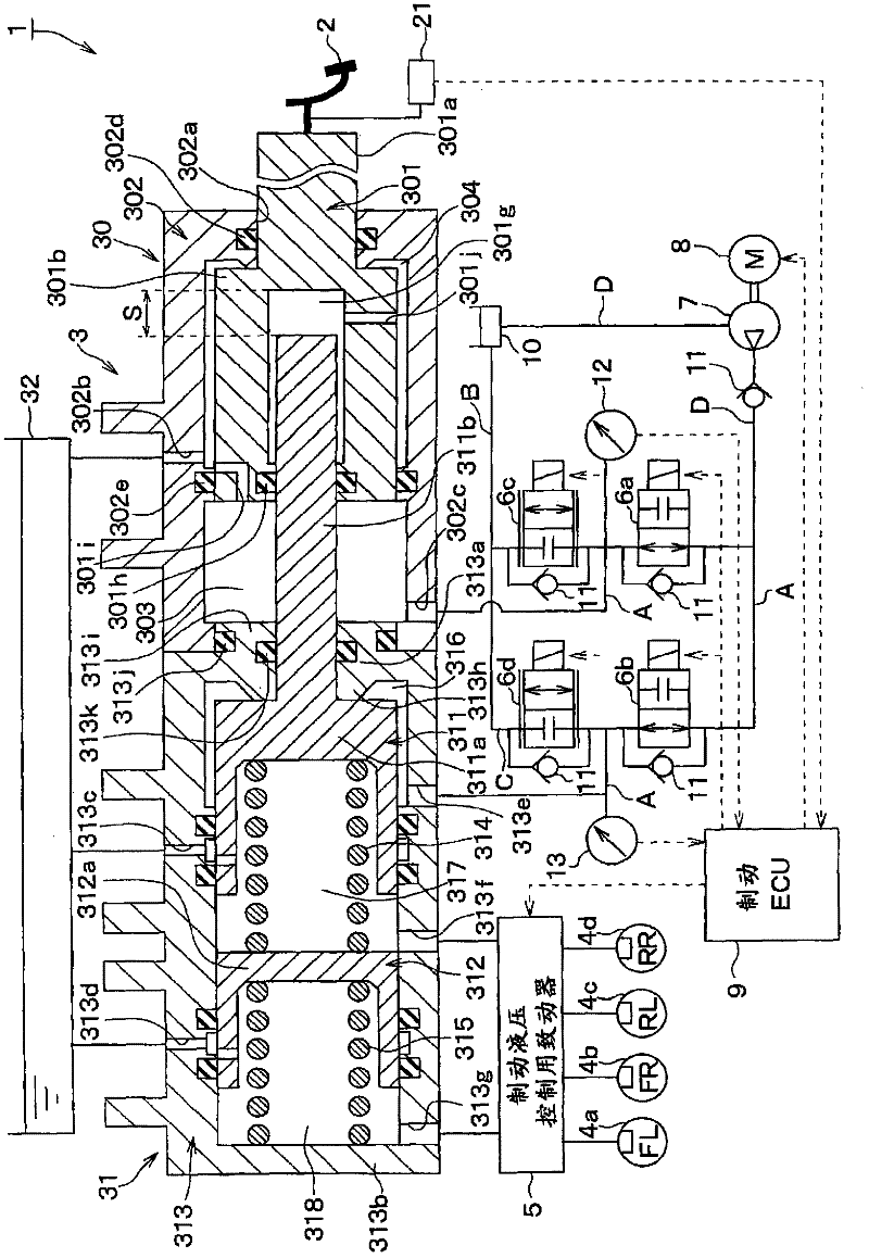
[0070] A second embodiment of the present invention will be described. This embodiment changes the structure of the M / C3 compared to the first embodiment. Others are the same as the first embodiment, so only the parts different from the first embodiment will be described.

[0071] image 3 The overall configuration of the vehicle brake device 1 according to the present embodiment is shown. As shown in the figure, in this embodiment, the bottom of the M / C piston 311 has an input shaft 311b protruding toward the input piston 301 side, and the input piston 301 is provided with a hollow portion 301g into which the input shaft 311b is inserted. The input shaft 311b is inserted from the entrance of the hollow portion 301g, and a gap S is provided between the bottom surface of the hollow portion 301g and the front end of the input shaft 311b. The inlet of the hollow portion 301g is provided with a seal member 301h made of an O-ring or the like, thereby ensuring the sealing propert...

no. 3 approach

[0076] A third embodiment of the present invention will be described. This embodiment has a pressure accumulator compared to the first embodiment, and the others are the same as the first embodiment, so only the parts different from the first embodiment will be described.

[0077] Figure 4 The overall configuration of the vehicle brake device 1 according to the present embodiment is shown. As shown in the figure, on the discharge side of the pump 7 in the pipe line D and at a position closer to the line A side than the check valve 11, there is brake fluid that can be pumped by the discharge operation of the pump 7. The accumulator 14 for accumulating pressure has a fifth control valve 6e formed of a normally closed solenoid valve at a position closer to the line A side than the accumulator 14 . In addition, the third pressure sensor 15 can detect the brake hydraulic pressure accumulated in the accumulator 14 (hereinafter referred to as accumulator pressure). When the thres...


PUM


Abstract

The invention discloses a braking device to guarantee a regeneration efficiency and eliminate invalid travel. A counter-force chamber changing counter-force hydraulic pressure along with the movement of an input piston and a drive hydraulic chamber connecting with the counter-force through a hydraulic circuit are disposed in the M / C. And the hydraulic circuit is provided with a first valve and pump, a second valve and pump, a third valve and pump and a fourth control valve and pump. Besides, the first control valve and the second valve are set to be a normally-closed electromagnetic valve in a disconnection state in an electrified state and in a connection state in a non-electrified state. According to the structure, when a regeneration association control is conducted normally, no M / C pressure is generated before generating a maximum regeneration braking that able to be generated through setting the second control valve in a disconnection state, so as to obtain the maximum regeneration efficiency. Besides, when the device is in the abnormal, since the second control valve is in a connection state, braking liquid in the counter-force chamber moves towards the drive hydraulic chamber through a pipeline. Therefore, invalid travel is eliminated and braking force is generated.

Description

technical field [0001] The present invention relates to a brake device capable of regenerative coordinated control in which service brakes and regenerative brakes are coordinated. Background technique [0002] Conventionally, regenerative cooperative control has been performed in order to recover energy during braking as regenerative energy. In coordinated regenerative control, when the driver depresses the brake pedal, regenerative braking occurs instead of normal braking. When the regenerative cooperative control is performed, the input piston is moved by depressing the brake pedal. When M / C pressure is generated, braking force based on normal braking is generated, resulting in a reduction in regeneration efficiency. [0003] In order to avoid this situation, Patent Document 1 proposes a vehicle braking device having a structure in which a stroke amount estimation corresponding to the braking amount of regenerative braking is provided between the input piston and the out...

Claims


Application Information

Patent Timeline
Patent Type & Authority Applications(China)
IPC IPC(8): B60T8/17B60T13/14
CPCB60T8/441B60T13/162B60T13/686
Inventor 石田聪
Owner ADVICS CO LTD
Why Eureka
Try Eureka