
A hydraulic regeneration system for excavator arm

A regenerative system and hydraulic technology, applied in the direction of mechanically driven excavators/dredgers, etc., can solve the problems of uncontrolled switching time, inability to regenerate, and low regeneration efficiency, so as to improve maneuverability, save costs, and ensure regeneration efficiency Effect

Active Publication Date: 2018-01-30
WEICHAI POWER CO LTD
View PDF6 Cites 0 Cited by
  • Summary
  • Abstract
  • Description
  • Claims
  • Application Information

AI Technical Summary

Problems solved by technology

[0008] Although flow regeneration can be performed in the above-mentioned prior art, the switching time between the regeneration flow and the main pump flow is not controlled, and it is possible that the main circuit is still in a conduction state when regeneration is required, and the pressure of the main pump is still higher than that of the rodless chamber of the cylinder. If the pressure is high, this situation will lead to low regeneration efficiency, or even failure to regenerate

Method used


Image

  • A hydraulic regeneration system for excavator arm
  • A hydraulic regeneration system for excavator arm

Examples


Embodiment Construction

[0024] The specific implementation manners of the present invention will be further described in detail below in conjunction with the accompanying drawings and embodiments. The following examples are used to illustrate the present invention, but are not intended to limit the scope of the present invention.

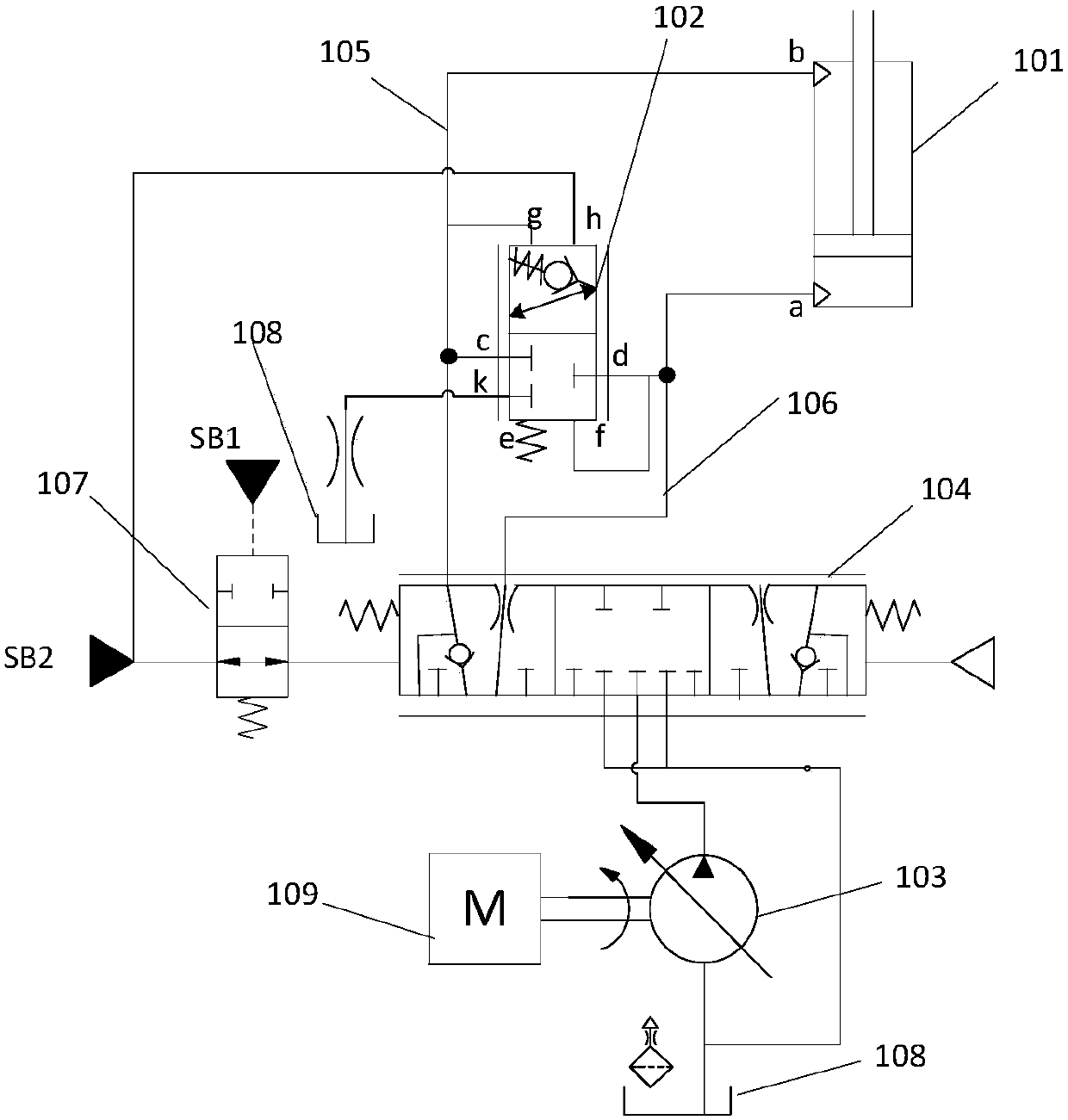
[0025] figure 1 It shows a hydraulic regeneration system of an excavator arm according to the present invention, including: an oil supply device, a boom regeneration hydraulic circuit, a swing control hydraulic oil circuit, and a hydraulic control main valve 104 arranged between the oil supply devices; The oil supply device is connected to the boom hydraulic regeneration circuit through the hydraulic control main valve 104;

[0026] The boom regenerative hydraulic circuit includes an oil supply pipeline 106 and an oil return pipeline 105, the oil outlet end of the oil supply pipeline 106 is connected to the rodless chamber of the boom cylinder 101, and the inlet of the oi...


PUM


Abstract

The invention provides a hydraulic regeneration system of a movable arm of an excavator. The hydraulic regeneration system comprises an oil supplying device, a movable arm regeneration hydraulic circuit, a rotary control hydraulic oil path and a hydraulic control main valve, wherein the oil supplying device is connected with the movable arm regeneration hydraulic circuit through the hydraulic control main valve; an oil supplying pipeline and an oil returning pipeline of the movable arm regeneration hydraulic circuit are connected with a movable arm oil cylinder and the hydraulic control main valve; a regeneration oil path inlet and a regeneration oil path outlet of an oil pressure regeneration control valve are connected with the oil supplying pipeline and the oil returning pipeline, respectively; a regeneration control oil path outlet of the oil pressure regeneration control valve is connected with a steering control oil path inlet of the hydraulic control main valve; a regeneration control oil path inlet of the hydraulic control main valve is connected with a movable arm descending control oil path; a regeneration switching control oil path inlet of the hydraulic control main valve is connected with the rotary control oil path; and a control oil path is further connected between the regeneration control oil path inlet and the control oil path inlet. Main pump flow (which is regenerated) and the movable arm oil cylinder can be reliably switched when the movable arm of the excavator is controlled to descend through the rotary movement of the movable arm of the excavator, and the regeneration efficiency is guaranteed.

Description

technical field [0001] The invention relates to the technical field of an excavator, in particular to a hydraulic regeneration system for an excavator arm. Background technique [0002] When the loads of the excavator with the load sensing system are different, there will be a pressure compensation loss. Especially in the action of "boom lowering + turning", the boom lowering action has a small pressure in the rod chamber and a large flow rate, while the turning action has a large pressure and a large flow rate. When the compound action of "boom down + swing", the inlet pressure of the main pump is equal to the swing pressure, there is a pressure compensation valve in the main valve controlling the boom, which can reduce the inlet pressure of the main pump to the level of the boom rod chamber pressure to ensure the smooth progress of the "boom lowering + turning" compound action, but because the flow of the boom lowering is relatively large, the main pump will be controlled...

Claims


Application Information

Patent Timeline
Patent Type & Authority Patents(China)
IPC IPC(8): E02F3/42
CPCE02F3/42
Inventor 刘林卢强董梁秦绪鑫
Owner WEICHAI POWER CO LTD
Learn More