Electronic component

A technology of electronic components and electrodes, which is applied to the field of electronic components with built-in capacitors, can solve problems such as irradiating laser beams, and achieve low ESL and easy installation

Active Publication Date: 2012-03-21
MURATA MFG CO LTD
View PDF3 Cites 3 Cited by
  • Summary
  • Abstract
  • Description
  • Claims
  • Application Information

AI Technical Summary

Problems solved by technology

Therefore, it is relatively difficult to form the via-hole conductors 606a, 606b for connecting the external terminal electrodes 504a, 504b.
In particular, since the sealing member 604 is provided, it is difficult to irradiate the laser beam at the correct position, so it is relatively difficult to form the via-hole conductors 606a, 606b to connect the external terminal electrodes 504a, 504b.

Method used


Image

  • Electronic component
  • Electronic component
  • Electronic component

Examples


no. 1 approach

[0045] Structure of Electronic Components

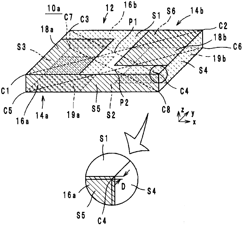
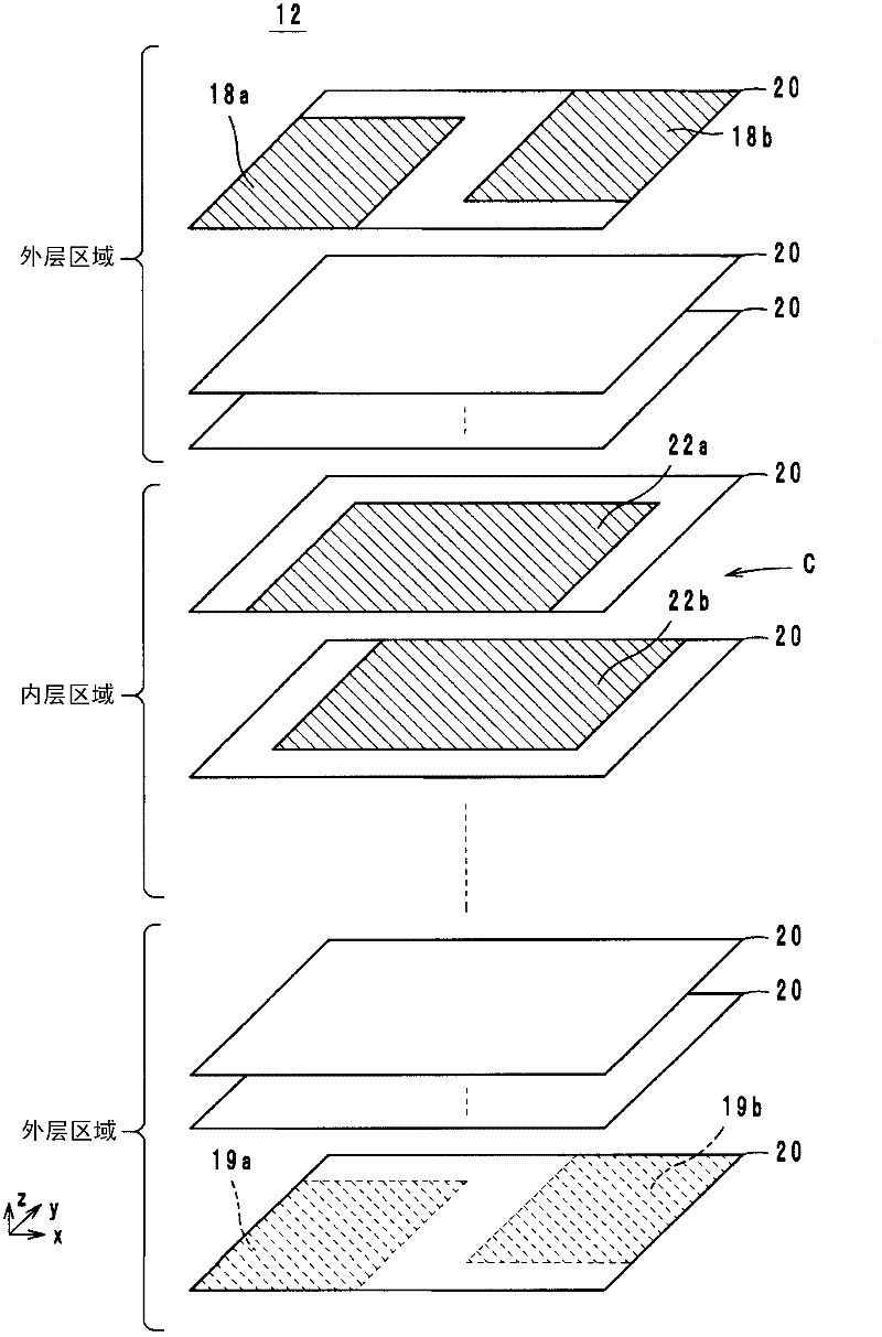
[0046] First, the configuration of the electronic component according to the first embodiment will be described with reference to the drawings. figure 1 It is an external perspective view and a partial enlarged view of the electronic component 10a which concerns on 1st Embodiment. figure 2 yes figure 1 An exploded perspective view of the laminated body 12 of the electronic component 10a. Hereinafter, the stacking direction of the stacked body 12 is referred to as the z-axis direction. When the laminated body 12 is planarly viewed from the z-axis direction, the long-side direction in which the long side of the main surface of the laminated body 12 extends is defined as the x-axis direction. The short direction in which the short sides of the laminated body 12 extend when the laminated body 12 is planarly viewed from the z-axis direction is defined as the y-axis direction.

[0047] The electronic part 10a is a chip capacitor suc...

no. 2 approach

[0105] Structure of Electronic Components

[0106] Next, the configuration of an electronic component 10d according to the second embodiment will be described with reference to the drawings. Figure 11 It is an external appearance perspective view of 10 d of electronic components concerning 2nd Embodiment. Figure 12 yes Figure 11 An exploded perspective view of the laminated body 12 of the electronic component 10d.

[0107] The electronic part 10d is a chip capacitor such as Figure 11 and Figure 12 As shown, there are laminated body 12, external electrodes 14 (14a, 14b), lead-out conductors 23 (23a, 23b), 24 (24a, 24b) (in Figure 11 not shown) and capacitor C (in Figure 11 not shown). The chip capacitor has a cuboid shape having dimensions of about 600 μm (x-axis direction)×about 300 μm (y-axis direction)×about 150 μm (z-axis direction). Since the appearance of the laminated body 12 of the electronic component 10d is the same as that of the laminated body 12 of th...


PUM


Abstract

In an electronic component, an external electrode (14a) includes a side surface electrode (16a) provided on a side surface (S5) and a substantially rectangular principal surface electrode (18a) that is connected to the side surface electrode (16a) and provided on a principal surface (S1) so as to be in contact with a (C1) corner of the principal surface (S1). An external electrode (14b) includes a side surface electrode (16b) that is connected to a capacitor conductor and provided on a side surface (S6) and a substantially rectangular principal surface electrode (18b) that is connected to the side surface electrode (16b) and provided on the principal surface (S1) so as to be in contact with a corner (C2), which is located opposite to the corner (C1), the principal surface electrode (18b) facing the principal surface electrode (16b) in an x-axis direction, in which long sides of the principal surface extend. Therefore, low ESL can be realized and installation in a circuit board is facilitated.

Description

technical field [0001] The present invention relates to electronic components, and particularly to electronic components incorporating capacitors. Background technique [0002] As a conventional electronic component, for example, a multilayer capacitor described in Patent Document 1 is known. This multilayer capacitor includes a capacitor body, a first external terminal electrode, a second external terminal electrode, and a capacitor. The capacitor body has a stacked structure composed of a plurality of stacked dielectric layers, and has a rectangular parallelepiped shape having a first main surface and a second main surface that extend along the surface direction of the dielectric layer and face each other. The first side surface and the second side surface, and the first end surface and the second end surface opposite to each other, and have the respective longitudinal dimensions of the first end surface and the second end surface longer than the respective lengths of the...

Claims


Application Information

Patent Timeline
Patent Type & Authority Applications(China)
IPC IPC(8): H01G4/30H01G4/005H01G4/232
CPCH01G4/30H01G4/232H01G4/012H01G4/35H01G4/12
Inventor 堤启恭
Owner MURATA MFG CO LTD
Why Eureka
Try Eureka