Rotary multiple-gear switch

A gear switch and rotary technology, applied in the field of rotary multi-speed switches, can solve the problems of not being able to quickly and accurately find the required gear, not having a limit function, increasing space accommodation, etc., and achieving a simple structure, Wide range of applications, easy to operate and use

Active Publication Date: 2014-01-22
ZHUHAI MEFO OPTICAL INSTR CO LTD
View PDF6 Cites 5 Cited by
  • Summary
  • Abstract
  • Description
  • Claims
  • Application Information

AI Technical Summary

Problems solved by technology

[0002] A switch refers to an electronic component that can open a circuit, interrupt the current, or cause it to flow to other circuits. At present, mechanical switches on the market are divided into different operation modes: push type, trigger type, toggle type, rotary type, rotary The multi-position switch is widely used in electrical fields such as fans, lamps, radios, stereos, etc. due to its advantages of convenient use, multi-position adjustment, and reliable positioning. At present, a rotary multi-position switch has appeared, but this Domestic products of switches have poor positioning and power-on reliability, but to ensure the reliability of positioning and power-on, the volume of the switch must be made relatively large, so that the corresponding need to increase space accommodation and increase production costs, in some accommodation space It is inconvenient for limited equipment, such as gun sights and other equipment, and foreign products can find a similar function selection switch, which is imported from Europe. It needs to be connected with a self-designed circuit to achieve brightness and multi-function adjustment. The price is similar to domestic switches. More than 15 times, there are also the problems of complex structure and high cost. Moreover, the existing rotary multi-position switch does not have the limit function. Yes, the existing multi-position rotary switch generally adopts two ways to use at night: use fluorescent paint on the identification mark, or use LED lighting to facilitate and accurately find the gear. These two ways are easy to expose yourself. If this method is not adopted, the required gear cannot be found quickly and accurately, and there is also a certain inconvenience

Method used


Image

  • Rotary multiple-gear switch
  • Rotary multiple-gear switch
  • Rotary multiple-gear switch

Examples


Embodiment Construction

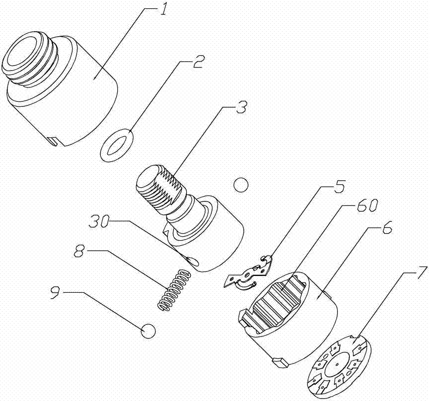
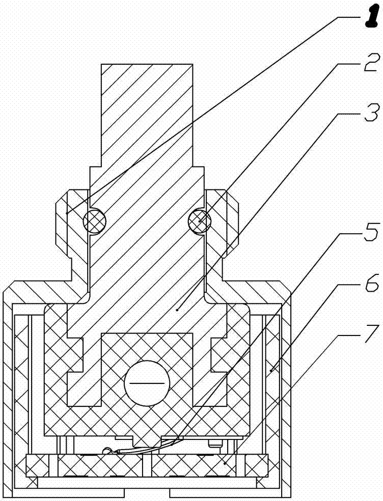
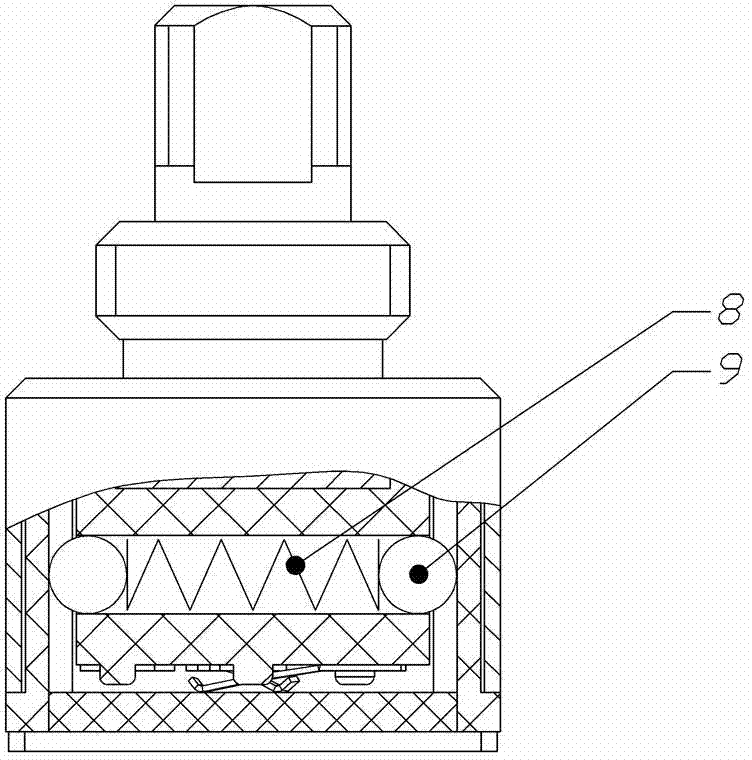
[0018] Such as figure 1 , figure 2 , image 3 , Figure 4 , Figure 5 , Image 6 As shown, the present invention includes a casing, a switch rotor 3 located in the cavity of the casing and rotatingly matched with the casing, and a rotary gear adjustment device, and the rotary gear adjustment device is connected to the switch rotor 3 and the switch rotor 3 respectively. The housing is connected to each other, and the gear adjustment is performed when the switch rotor 3 rotates relative to the housing. An annular groove 60 is provided on the inner side wall of the housing. The housing includes a switch seat 1 and a switch stator 6. The switch The seat 1 is set on the outer wall of the switch stator 6 to match the switch stator 6, the switch seat 1 presses the switch rotor 3, and the annular groove 60 is arranged on the switch stator 6 , the lower end of the switch rotor 3 is located in the switch stator 6, the top of which passes through the switch seat 1, the lower end of...


PUM


Abstract

The invention discloses a rotary multiple-gear switch which has a simple structure, a small volume and low cost and can position rapidly and correctly by one-way rotation. The rotary multiple-gear switch comprises a shell, a switch rotor (3) and a rotary gear adjustment device; the rotary gear adjustment device is connected with both the switch rotor (3) and the shell; the switch rotor (3) is used to adjust the gear when rotating relative to the shell; the rotary gear adjustment device is directly arranged in the shell without being connected with an external circuit board, thus the occupied space is greatly reduced; the inner side wall of the shell is provided with an annular groove (60); and the lower end of the switch rotor (3) is provided with a through hole (30), a compression spring (8) and a rolling ball (9), wherein the compression spring (8) and the rolling ball (9) are arranged in the through hole (30), and the rolling ball (9) is elastically compressed in the annular groove (60) under the action of the compression spring (8).

Description

technical field [0001] The invention relates to a rotary multi-position switch. Background technique [0002] A switch refers to an electronic component that can open a circuit, interrupt the current, or cause it to flow to other circuits. At present, mechanical switches on the market are divided into different operation modes: push type, trigger type, toggle type, rotary type, rotary The multi-position switch is widely used in electrical fields such as fans, lamps, radios, stereos, etc. due to its advantages of convenient use, multi-position adjustment, and reliable positioning. At present, a rotary multi-position switch has appeared, but this Domestic products of switches have poor positioning and power-on reliability, but to ensure the reliability of positioning and power-on, the volume of the switch must be made relatively large, so that the corresponding need to increase space accommodation and increase production costs, in some accommodation space It is inconvenient f...

Claims


Application Information

Patent Timeline
Patent Type & Authority Patents(China)
IPC IPC(8): H01H19/03H01H19/04H01H19/10H01H19/28
Inventor 李攀峰伍超球
Owner ZHUHAI MEFO OPTICAL INSTR CO LTD
Why Eureka
Try Eureka