
Flat wiper blade

A wiper and scraper technology, which is applied in the field of flat wiper scrapers, can solve the problems of high assembly cost and large expenditure

Active Publication Date: 2012-04-11
VALEO SYST DESSUYAGE
View PDF9 Cites 28 Cited by
  • Summary
  • Abstract
  • Description
  • Claims
  • Application Information

AI Technical Summary

Problems solved by technology

The disadvantage in this case is specifically the greater outlay in terms of assembly and the associated high assembly costs due to the large number of individual components

Method used


Image

  • Flat wiper blade
  • Flat wiper blade
  • Flat wiper blade

Examples


Embodiment Construction

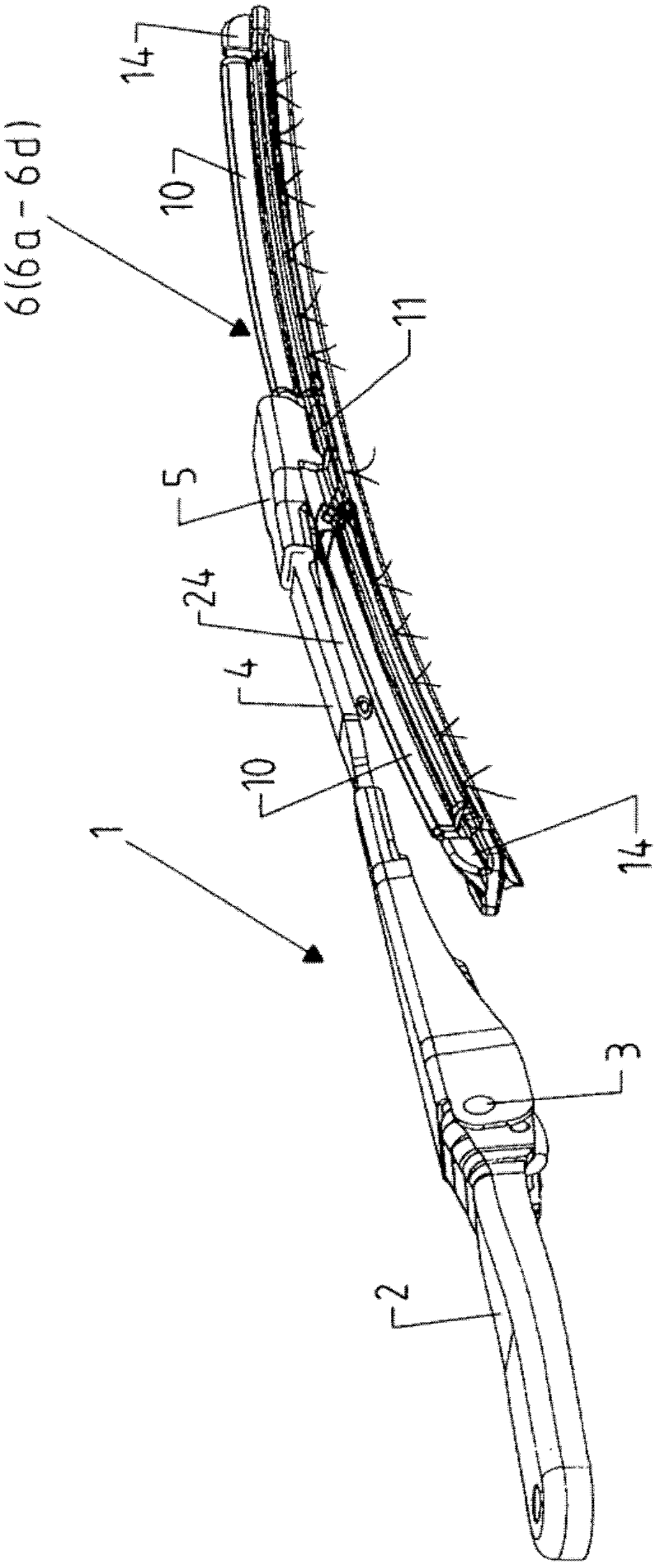
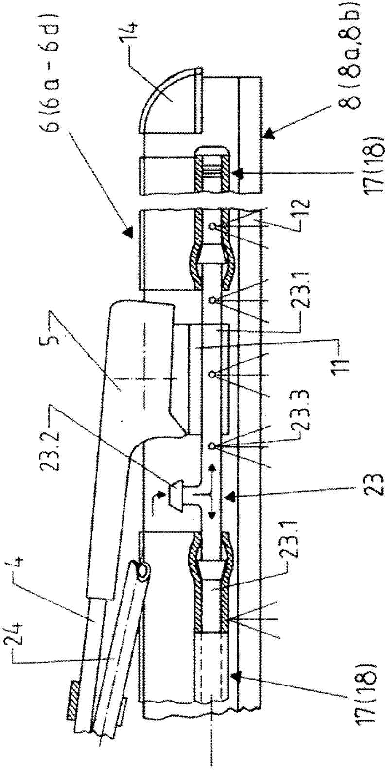
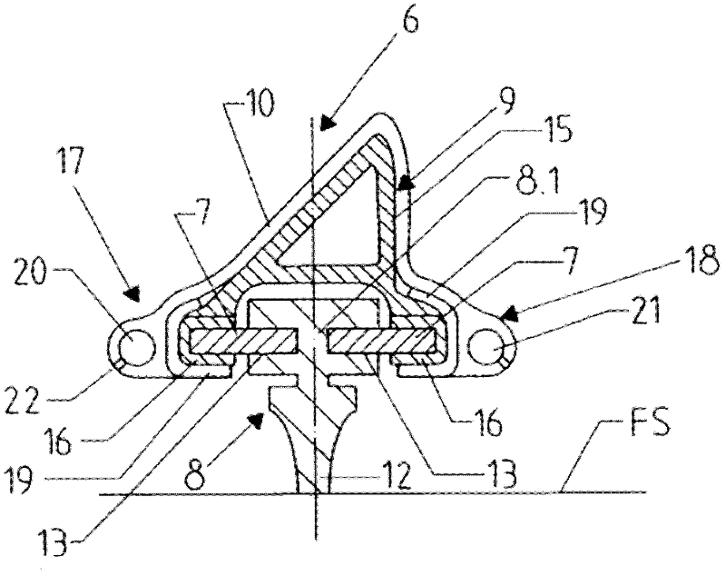
[0022] exist Figure 1-7 Among them, 1 is the wiper arm of the windshield wiper module for the vehicle windshield FS, especially for the front windshield of the vehicle. The wiper arm 1 comprises, in a known manner, a pivot part 2 and a wiper arm element 4 (wiper lever), via which the wiper arm 1 can be mounted on a not shown wiper shaft, which A wiper arm element 4 is hinged on the pivot part 2 via a wiper arm link 3, said wiper arm element being provided at its end remote from the pivot part 2 with a wiper-side adapter 5 for wiping Removable flexible fixation of wiper blades, e.g. image 3 Wiper blade 6 in.

[0023] The wiper blade 6 is configured as a flat wiper blade and comprises for this purpose: at least two flat elastic rails 7 made of elastic metal material (for example spring steel); a wiper rubber 8; two spoilers two housing-shaped spoiler elements 10 forming the upper side of the wiper blade 6 ; and a wiper blade adapter 11 for detachable flexible connection to ...


PUM


Abstract

Flat wiper blade for use in windscreen wiper modules of vehicles, essentially consisting of a wiping rubber in addition to two spring rails, extending in the longitudinal direction of the wiper blade, spaced apart from one another and receiving the wiping rubber in a subsection between them, which each respectively project over the wiping rubber on the wiper blade longitudinal sides and with at least one jet or injection strip provided on one longitudinal side of the wiper blade, having at least one injection or washing duct with a large number of jet or injection openings for application of a washing and cleaning fluid to a vehicle windscreen and which, with use of clip-like fixtures spanning the wiper blade on the upper side of the wiper blade, is retained on the external peripheries of the spring rails.

Description

technical field [0001] The invention according to the preamble of claim 1 or 8 of the patent relates to a flat wiper blade, and in this case in particular to a flat wiper blade which in at least one longitudinal direction of the wiper blade On the side there is at least one spray or washer duct with a plurality of spray or spray openings for applying washer and cleaning fluid to the vehicle windscreen. Background technique [0002] Flat wiper blades are known in various embodiments. Also known in particular is a flat wiper blade (DE 103 35 394 A1), which has: two flat elastic rails spaced apart from each other, which extend in the longitudinal direction of the wiper blade, and a wiping rubber forming a wiping lip Parts, wherein the elastic guide rails are respectively received in the grooves on the longitudinal sides of the wiping rubber on part of their width, and thus the wiping rubber is received between the guide rails in the part of the wiping rubber held between the g...

Claims


Application Information

Patent Timeline
IPC IPC(8): B60S1/52B60S1/38
CPCB60S1/381B60S1/3808B60S1/3862B60S1/3879B60S1/524B60S1/3805B60S1/3886B60S1/42
Inventor B.埃格纳-瓦尔特M.肖布尔
Owner VALEO SYST DESSUYAGE
Features
  • Generate Ideas
  • Intellectual Property
  • Life Sciences
  • Materials
  • Tech Scout
  • Unparalleled Data Quality
  • Higher Quality Content
  • 60% Fewer Hallucinations
Learn More