Surge suppression circuit and switching control circuit

A technology for suppressing circuits and switching control, applied in control/regulating systems, output power conversion devices, electrical components, etc., to solve problems such as shortened service life, increased circuit costs, and damage

Inactive Publication Date: 2012-05-16
GREEN SOLUTION TECH CO LTD
View PDF4 Cites 4 Cited by
  • Summary
  • Abstract
  • Description
  • Claims
  • Application Information

AI Technical Summary

Problems solved by technology

[0004] Such a phenomenon will cause the withstand voltage level of transistors M1 and M2 to be even as figure 1 When the controller 10 in the shown embodiment is connected to the connection point of the transistors M1 and M2, the withstand voltage level of the controller 10 also needs to be increased at the same time
This will not only increase the overall circuit cost, but also the voltage range of the voltage signal Vp will vary with different circuit designs, and may still exceed the withstand voltage of the controller and transistor, resulting in shortened service life or even damage

Method used


Image

  • Surge suppression circuit and switching control circuit
  • Surge suppression circuit and switching control circuit
  • Surge suppression circuit and switching control circuit

Examples


Embodiment Construction

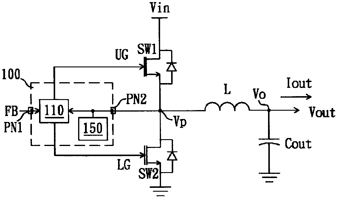
[0039] See image 3 , image 3 It is a circuit diagram of a conversion control circuit according to a preferred embodiment of the present invention. The conversion control circuit of this embodiment is used to control a conversion circuit to transmit power from an input power source Vin to an output terminal Vo to provide a stable output voltage Vout or a stable output current Iout. The conversion circuit includes an inductor L and an output terminal Vo. Output capacitor Cout. The switching control circuit includes two switching units SW1 and SW2, a control circuit 110 and a surge suppression circuit 150. The control circuit 110 and a surge suppression circuit 150 can be packaged in a single package to form a controller 100. The two switching units SW1 and SW2 are connected in series between the input power Vin and the ground potential, and the connection point of the two switching units SW1 and SW2 is coupled to one end of the inductor L, and the other end of the inductor L is...


PUM


Abstract

The invention provides a surge suppression circuit and a switching control circuit which are used for filtering voltage concussion caused by an inductor. The surge suppression circuit comprises an energy release path and a sensing circuit, wherein one end of the energy release path is coupled with the connecting end of a circuit, and the other end of the energy release path is coupled with a reference potential; and the sensing circuit is coupled with the connecting end, a sensing circuit of a switching unit is provided with a high-pass element, and the high-pass element is used for conducting the energy release path of the switching unit when the voltage of the connecting end of the switching unit has radio-frequency signals.

Description

Technical field [0001] The invention relates to a surge suppression circuit and a conversion control circuit, in particular to a surge suppression circuit and a conversion control circuit for suppressing high-frequency oscillation signals of potential caused by inductance elements. Background technique [0002] See figure 1 , figure 1 It is a circuit diagram of a traditional DC-to-DC step-down conversion circuit. The DC-DC step-down conversion circuit includes a controller 10, transistors M1 and M2, an inductor L, and an output capacitor Cout. The transistors M1 and M2 are connected in series to an input power source Vin and a ground potential. One end of the inductor L is coupled to the junction of the transistors M1 and M2, and the other end is coupled to the output capacitor Cout to output an output voltage Vout. The controller 10 generates a control signal UG and LG according to the output voltage Vout and the voltage signal Vp of the transistors M1 and M2 to control the tra...

Claims


Application Information

Patent Timeline
Patent Type & Authority Applications(China)
IPC IPC(8): H02M1/32H02M3/155
CPCH02M2001/0038H02M3/156H02M1/0038
Inventor 李立民余仲哲徐献松陈继明
Owner GREEN SOLUTION TECH CO LTD
Why Eureka
Try Eureka