Cross-coupling control apparatus and RF cavity filter having the same

A cross-coupling and adjusting device technology, which is applied to waveguide devices, resonators, electrical components, etc., can solve problems such as the inability to substantially change the physical length of the coupling rod, difficulty in industrial use, and inability to adjust the coupling amount of the resonator.

Inactive Publication Date: 2012-05-16
ACE TECH
View PDF3 Cites 4 Cited by
  • Summary
  • Abstract
  • Description
  • Claims
  • Application Information

AI Technical Summary

Problems solved by technology

[0017] However, the conventional cross-coupling structure using the coupling rod 200 has the problem that the amount of coupling between the cross-coupled resonators cannot be adjusted.
The amount of cross-coupling is determined by the size of the coupling rod. Therefore, according to the prior art, when a fully coupled cross-coupling cannot be obtained, a coupling rod of another size must be replaced, and the coupling cannot be adjusted when the coupling rod 200 is installed. quantity
[0018] In order to solve this existing problem, a method of inserting a tuning screw at the installation position of the coupling rod to adjust the coupling amount has also been proposed, but this method cannot be substantially The method of changing the physical length of the coupling rod accurately, the coupling amount changed by the tuning screw is small, and there are difficulties in industrial application

Method used


Image

  • Cross-coupling control apparatus and RF cavity filter having the same
  • Cross-coupling control apparatus and RF cavity filter having the same
  • Cross-coupling control apparatus and RF cavity filter having the same

Examples


Embodiment Construction

[0048] Since the present invention can be modified variously and has various embodiments, it will be described in detail by illustrating a specific embodiment in each drawing. However, this does not mean that the present invention is limited to specific embodiments, and it should be understood that changes, equivalents, and substitutes included in the spirit and technical scope of the present invention are all included.

[0049] Hereinafter, preferred embodiments of the present invention will be described in detail with reference to the accompanying drawings.

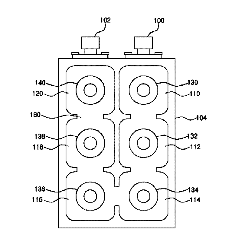
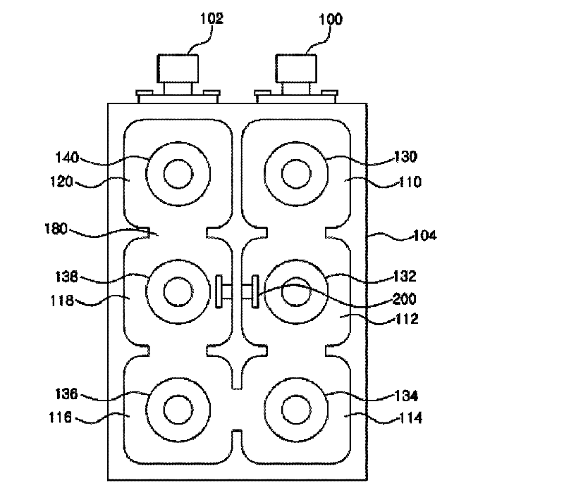
[0050] For ease of description, the independent structure of the cross-coupling adjustment device according to various embodiments of the present invention will be described first, and then the structure in which the cross-coupling adjustment device is arranged in the RF cavity filter will be described.

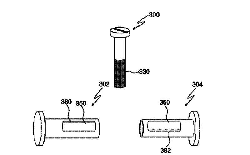
[0051] image 3 It is an exploded perspective view showing the cross-coupling adjustment device according to the fi...


PUM


Abstract

The present invention relates to a cross-coupling control apparatus and an RF cavity filter having the same. The cross-coupling control apparatus comprises: a female coupling bolt, which has a cavity formed inside and a 1st hole formed on one surface; a male coupling bolt, which is inserted into the cavity that is formed in the female coupling bolt and has a 2nd hole formed on one surface in correspondence with the 1st hole; ; control bolts, which are inserted into the female coupling bolt and the male coupling bolt through the 1st and 2nd holes, come in contact with a 1st interface which is one of the interfaces of the 1st hole and with a 2nd interface which is one of the interfaces of the 2nd hole, and have a thread with a pattern of grooves and protrusions formed on at least part of a side surface, wherein the physical length of a coupling assembly formed by joining the female coupling bolt and the male coupling bolt is adjusted by moving the female coupling bolt in a 1st direction and the male coupling bolt in a 2nd direction opposite to the 1st direction, through the rotation of the control bolt. This apparatus has an advantage that a cross-coupling amount can be adaptively controlled.

Description

technical field [0001] RF cavity filter The present invention relates to a cross-coupling adjustment device and an RF cavity filter including the device, more particularly to a method for forming a notch for adjusting the edge (skirt) characteristic of the filter A cross-coupling adjustment device and an RF cavity filter including the device. Background technique [0002] The RF cavity filter is a device that forms multiple cavities inside the filter and only allows signals in the frequency band to pass through. It is used in places where high-power frequency signals are applied, such as base stations. [0003] figure 1 It is a plan view showing the internal structure of a general existing RF cavity filter. [0004] like figure 1 As shown, a general existing RF cavity filter includes an input terminal 100, an output terminal 102, a housing 104, a plurality of cavities 110, 112, 114, 116, 118, 120 defined by the housing 104 and the partition, accommodated in Multiple reso...

Claims


Application Information

Patent Timeline
Patent Type & Authority Applications(China)
IPC IPC(8): H01P1/20H01P7/06
CPCH01P1/2084H01P1/2053H01P1/20H01P7/06
Inventor 李乘哲
Owner ACE TECH
Why Eureka
Try Eureka