Stocking sheathing tube for silk stocking heat transfer machine

A thermal transfer printing machine and silk stocking technology, applied in rotary printing machines, printing machines, transfer printing, etc., can solve problems such as uneven thermal transfer pressure, poor printing fastness, and unusable silk stockings

Inactive Publication Date: 2012-06-13
刘磊
View PDF5 Cites 0 Cited by
  • Summary
  • Abstract
  • Description
  • Claims
  • Application Information

AI Technical Summary

Problems solved by technology

[0003] In order to solve the problem of poor printing fastness caused by thermal transfer printing and uneven pressure for silk stockings and other light

Method used


Image

  • Stocking sheathing tube for silk stocking heat transfer machine
  • Stocking sheathing tube for silk stocking heat transfer machine
  • Stocking sheathing tube for silk stocking heat transfer machine

Examples


Embodiment Construction

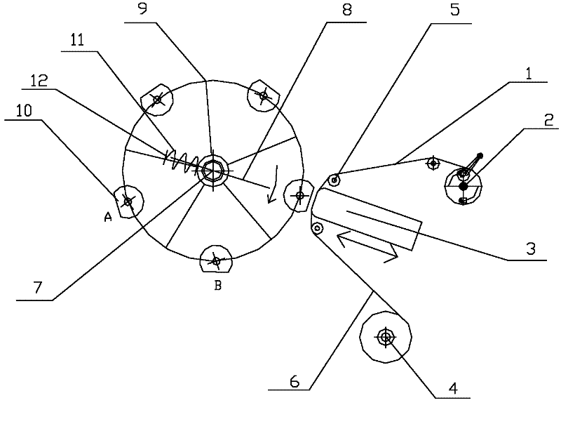
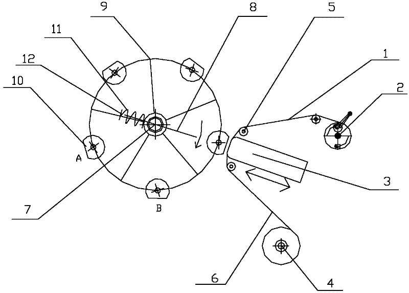
[0008] Referring to the accompanying drawings, this embodiment consists of a transfer part and a preheating part:

[0009] Transfer part: the transfer film 1 is wound on the transfer film unwinding frame 2, the transfer film 1 goes around the surface of the ironing head 3 through the guide wheel 5, the ironing head 3 can move in the direction of the arrow in the figure, and the transfer film 1 After the pattern transfer, the remaining bottom film 6 is rolled up on the bottom film winding frame 4, and the iron head 3 is heated internally, and the temperature of the iron head 3 is 120 plus or minus 2 degrees.

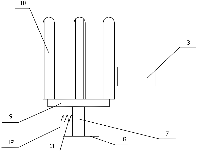
[0010] Preheating part: the base 7 is installed on the track 8 and can slide along the track 8, the bracket 9 is installed on the base 7, the bracket 9 can rotate around the base 7 in the direction of the arrow in the figure, and the preheating sock tube 10 is installed on the bracket 9 Above, the direction of the preheated sock tube 10 facing the perm 3 is a plane, which...


PUM


Abstract

The invention discloses a stocking sheathing tube for a silk stocking heat transfer machine and relates to the field of marking heat transfer in the production process of silk stockings, solving the problems that heat transfer cannot be applied to light and thin textiles incapable of resisting high temperature, such as silk stockings and the like and the printing fastness is poor due to non-uniformity of pressure. According to the stocking sheathing tube for the silk stocking heat transfer machine, which is provided by the invention, a plane is formed in the direction of the preheated stocking sheathing tube, which is opposite to an ironing head, and is matched with a surface plane of the ironing head. Due to the adoption of the design, the stocking sheathing tube has the advantages of continuous production and heat transfer production on the light and thin textiles incapable of resisting the high temperature as well as uniformity for printing fastness.

Description

Technical field: [0001] The invention relates to the field of marking thermal transfer printing in the production process of stockings. Background technique: [0002] Thermal transfer printing is a widely used printing technology. In this process, the pattern is pre-printed on the surface of the film. We call this film with transfer printing pattern transfer film; and then maintain a certain temperature and Under the condition of pressure, the exquisite pattern on the transfer film is transferred to the surface of the product. After forming, the ink layer and the surface of the product are melted into one, which is realistic and beautiful, and greatly improves the grade of the product. The thermal transfer process is applied to the surface of various ABS, PP, plastic, wood, coated metal, T-shirts and other products, but due to the high temperature of thermal transfer, the printed object is required to be able to withstand high temperature. The current situation in T-shirts ...

Claims


Application Information

Patent Timeline
IPC IPC(8): B41F16/02
CPCD06B11/0076
Inventor 不公告发明人
Owner 刘磊
Why Eureka
Try Eureka