Numerically controlled spiral bevel gear grinding machine

A technology of spiral bevel gears and gear grinding machines, which is applied in the direction of gear teeth manufacturing devices, gear cutting machines, belts/chains/gears, etc. It can solve problems such as excessive clearance, inability to adjust the grinding wheel, and increase vibration, so as to reduce grinding Effect of temperature, simplification of grinding process, and reduction of contact area

Active Publication Date: 2012-09-19
天津第一机床有限公司
View PDF9 Cites 12 Cited by
  • Summary
  • Abstract
  • Description
  • Claims
  • Application Information

AI Technical Summary

Problems solved by technology

The eccentricity of the grinding wheel installation, the uneven thickness of the grinding wheel, the unbalance of the main shaft, and the adsorption of the coolant by the grinding wheel will increase the vibration. These vibrations will not only affect the processing quality of the gear grinding machine, but also shorten the grinding time. The main shaft life of the machine and the life of the grinding wheel increase the number of grinding wheel corrections and the consumption of dressing diamonds, etc.
In addition, the balance adjustment of the grinding wheel is to adjust the grinding wheel adjustment block through the balance frame. Generally, it is carried out when replacing the new grinding wheel, and the gr

Method used


Image

  • Numerically controlled spiral bevel gear grinding machine
  • Numerically controlled spiral bevel gear grinding machine
  • Numerically controlled spiral bevel gear grinding machine

Examples


Embodiment Construction

[0030] In order to further understand the invention content, characteristics and effects of the present invention, the following examples are given, and detailed descriptions are as follows in conjunction with the accompanying drawings:

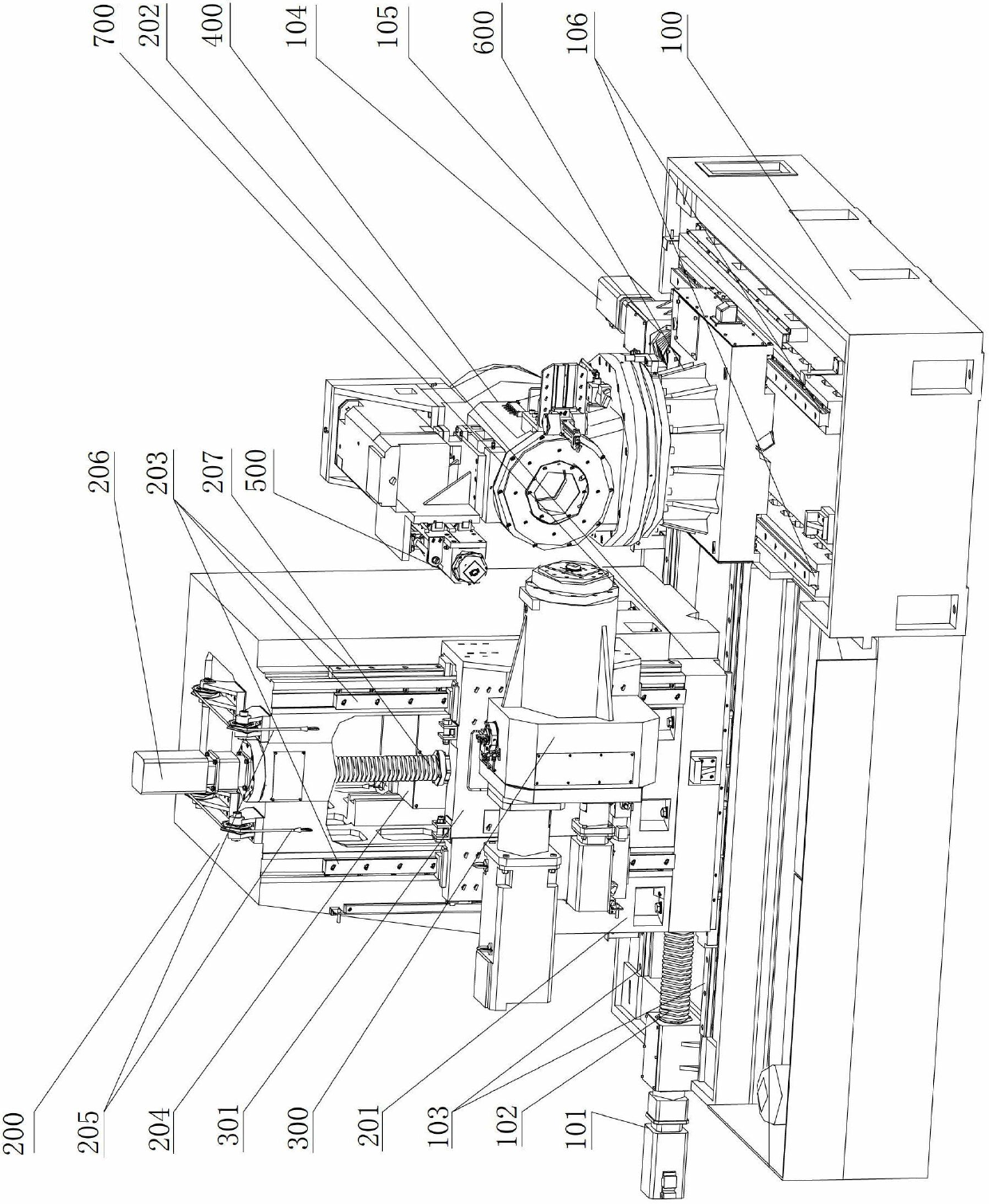
[0031] see Figure 1-Figure 7 , CNC spiral bevel gear grinding machine, including bed 100, column 200, grinding wheel headstock 300, workpiece headstock 400, grinding wheel correction mechanism 500, rotary table 600, electrical system, pneumatic system and hydraulic system, the electrical system , pneumatic system and hydraulic system are not shown in the figure. The rotary table is installed on the bed through the second linear guide rail 106, the workpiece spindle box 400 is installed on the rotary table, and the second ball screw 105 is driven by the second servo motor 104 to make the rotary table 600 move along the second linear guide rail 106. Move back and forth on the bed. A grinding wheel correction mechanism is installed on the wor...


PUM


Abstract

The invention relates to a numerically controlled spiral bevel gear grinding machine, comprising a bed, an upright, a grinding wheel spindle box, a workpiece spindle box, a grinding wheel dressing mechanism, a rotary worktable, an electrical system, a pneumatic system and a hydraulic system, and being characterized in that the bed is formed into an L-shaped structure having a slope on the surface thereof; a chip groove is formed at one side edge of the outer side of the bed, and an hollow upper upright is mounted on the bed through a sliding plate; the wall-mounted grinding wheel spindle box is mounted on the outer wall of the upper upright; a balance weight mechanism is arranged in the upper upright; a gear clearance eliminating mechanism is arranged on the workpiece spindle box; the grinding wheel spindle box employs a dual-shaft structure of a grinding wheel spindle and an eccentric spindle; an online dynamic balance device is arranged in the grinding wheel spindle box; and an online measuring device is mounted under the right side of the grinding wheel spindle. The numerically controlled spiral bevel gear grinding machine has the following advantages that: chip discharge is smooth and convenient; the degree of balance of the grinding wheel spindle is automatically adjusted through the online dynamic balance device; the rotary worktable is high in positioning accuracy and high in driving torque, and has a self-locking function; the gap of the workpiece spindle box is simple and convenient for clearance adjustment; and problems of unsteady transmission, and large gap and high noise of the gears are solved.

Description

technical field [0001] The invention belongs to the technical field of spiral bevel gear processing machine tools, in particular to a numerically controlled spiral bevel gear grinding machine. Background technique [0002] The CNC spiral bevel gear grinding machine is used for high-speed and precise grinding of spiral bevel gears. Its purpose is to correct the deformation of the gear heat treatment, improve the precision and smoothness of the tooth surface, and meet the requirements of stable transmission, noise reduction and high precision. [0003] The CNC rotary table is the core component of the gear grinding machine. The movement accuracy, bearing capacity, and ability to deal with impacts of the CNC rotary table are related to the production and processing capabilities and precision of the entire machine tool. The current application status of CNC rotary table is not ideal. At present, the transmission modes of the CNC rotary table include worm gear transmission and g...

Claims


Application Information

Patent Timeline
IPC IPC(8): B23F9/02B23F23/00B23Q5/10B23Q1/26B23Q11/00B23Q17/00
Inventor 王秀梅王景召沈凤美刘福聪祁志良胡光曦吴杰王威刘新瑞
Owner 天津第一机床有限公司
Why Eureka
Try Eureka