

Upper cutter shaft moving mechanism in edge trimmer
A technology of moving mechanism and trimming machine, which is applied in metal processing and other directions, can solve the problems of workpiece machining accuracy, gap and gap unevenness that affect the moving accuracy of the cutter shaft, and achieve the goal of improving production efficiency, ensuring detection accuracy, and strong practicability Effect
Inactive Publication Date: 2012-11-14
JIANGSU YAWEI MACHINE TOOL
View PDF0 Cites 0 Cited by
- Summary
- Abstract
- Description
- Claims
- Application Information
AI Technical Summary
Problems solved by technology
[0003] The purpose of the present invention is to provide a moving mechanism for the upper cutter shaft in the trimming machine, which solves the problems of the existing trimming machine due to the gap and uneven gap between the guide rail plate and the frame, which directly affects the moving accuracy of the cutter shaft and the processing of the workpiece. lack of precision
Method used
View moreImage
Smart ImageViewing Examples

Examples
Embodiment Construction
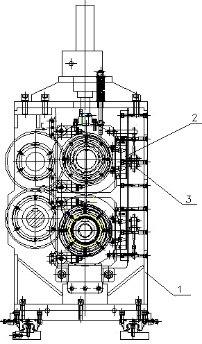
[0009] Further illustrate the present invention in conjunction with accompanying drawing and embodiment, as figure 1 As shown, the present invention arranges a linear guide rail 2 and a linear displacement sensor 3 on the trimming body 1, the linear guide rail 2 is fixed on the body 1, the fixed end of the linear displacement sensor 3 is fixed on the body 1, and the movable end of the linear displacement sensor 3 Installed on the guide rail slider; the linear displacement sensor adopts PY2-C-50 (GEFRAN).
Login to View More PUM
 Abstract
The invention relates to an upper cutter shaft moving mechanism in an edge trimmer, which belongs to the field of the edge trimming mechanical technology. Witht the arrangement of a linear guide rail and a linear displacement sensor on the edge trimmer, the problem of the edge trimmer that the moving precision of a cutter shaft and the processing precision of a manufactured piece are directly affected because a gap between the guide rail plate and the rack is uneven is overcome. According to the upper cutter shaft moving mechanism in an edge trimmer, the linear guide rail is installed on an engine body, a guide rail sliding block is installed on the upper sliding block of the cutter shaft, and thus the problem is solved by moving the linear guide rail. The precision of all aspects is guaranteed, the moving distance is measured by the linear displacement sensor to guarantee the detection precision and provide convenience for improving the production efficiency, and thus the upper cutter shaft moving mechanism in an edge trimmer has the advantage of strong practicality.
Description
technical field [0001] The invention relates to a moving mechanism for an upper knife shaft in an edge trimming machine, and belongs to the technical field of edge trimming machinery. Background technique [0002] In the process of sheet material processing, it is necessary to carry out edge trimming processing on the sheet material through an edge trimmer. The two sides of the upper slider of the existing edge trimmer cutter shaft are equipped with guide rail plates, which move up and down in the frame, so that due to Processing and assembly errors, there are problems such as gaps and gaps between the guide rail plate and the frame, which directly affect the movement accuracy of the cutter shaft and the processing accuracy of the workpiece. Contents of the invention [0003] The purpose of the present invention is to provide a moving mechanism for the upper cutter shaft in the trimming machine, which solves the problems of the existing trimming machine due to the gap and ...
Claims
Login to View More Application Information
Patent Timeline
 Patent Type & Authority Applications(China)
IPC IPC(8): B26D7/00
Inventor 潘恩海张峰居春红周德宇黄旸刘涛
Owner JIANGSU YAWEI MACHINE TOOL